background image

SE-SR2

Operating instructions SE-SR2
826002433-EN-Rev.C

20

EC declaration of conformity


EU DECLARATION OF CONFORMITY 

UE DICHIARAZIONE DI CONFORMITA' 

UE DECLARACIÓN DE CONFORMIDAD 

 UE DÉCLARATION DE CONFORMITÉ 

EU KONFORMITÄTSERKLÄRUNG 

EU CONFORMITEITSVERKLARING 

 EU FÖRSÄKRAN OM ÖVERENSSTÄMMELSE


EC-326_1          Pag. 1 of 1 


Apparatus / Apparato / Aparato / Appareil / Gerätetyp / Apparaatmodel / Apparatmodell


SE-SR2; EMERGENCY - STOP SAFETY DEVICE 


and all its models / e tutti i suoi modelli / y todos sus modelos / et tous ses modèles / und seine modelle / en al haar modellen / och alla sina modeller 


Manufacturer / Produtore / Fabricante / Fabricant / Hersteller / Fabrikant / Tillverkaren 


Datalogic S.r.l.  

Via S.Vitalino 13 - 40012 Calderara di Reno - Bologna ITALY 


This declaration of conformity is issued under the sole responsability of the manufacturer / La presente dichiarazione di conformità è rilasciata sotto la 
responsabilità  esclusiva  del  fabbricante  /  La  presente  declaración  de  conformidad  se  expide  bajo  la  exclusiva  responsabilidad  del  fabricante  /  La  
présente    déclaration    de    conformité    est    établie    sous    la    seule  responsabilité  du  fabricant / Die  alleinige  Verantwortung  für  die  Ausstellung  
dieser    onformitätserklärung    trägt    der    Hersteller  /  Deze    conformiteitsverklaring    wordt    verstrekt    onder    volledige    verantwoordelijkheid    van    de  
fabrikant / Denna  försäkran  om  överensstämmelse  utfärdas  på  tillverkarens  eget  ansvar. 


The object of the declaration described above is in conformity with the relevant Union harmonization legislation: / L'oggetto della dichiarazione di cui 
sopra è conforme alla pertinente normativa di armonizzazione dell'Unione: / El  objeto  de  la  declaración  descrita  anteriormente  es  conforme  con  la  
legislación  de  armonización  pertinente  de  la Unión: / L’objet  de  la  déclaration  décrit  ci-dessus  est  conforme  à  la  législation  d’harmonisation  
de  l’Union  applicable: / Der  oben  beschriebene  Gegenstand  der  Erklärung  erfüllt  die  einschlägigen  Harmonisierungsrechtsvorschriften  der 
Union: / Het  hierboven  beschreven  voorwerp  is  in  overeenstemming  de  desbetreffende  harmonisatiewetgeving  van  de  Unie: / Föremålet  för  
försäkran  ovan  överensstämmer  med  den  relevanta  harmoniserade  unionslagstiftningen:  


2014/30/EU EMC Directive 

 2006/42/EC Machinery Directive 

2011/65/EU RoHS Directive 


References  to  the  relevant  harmonised  standards:  /  Riferimento  alle  pertinenti  norme  armonizzate:/  Referencias  a  las  normas  armonizadas:  / 
Références    des    normes    harmonisées:  /  Angabe    der    einschlägigen    harmonisierten    Normen:  /  Vermelding    van    de    toegepaste    relevante  
geharmoniseerde  normen: / Hänvisningar till de relevanta harmoniserade standarder: 


EN


ISO


13849-1:2015 

S

AFETY OF MACHINERY 

--


S

AFETY

-

RELATED PARTS OF CONTROL SYSTEMS 


P

ART 

1:


G

ENERAL 

P

RINCIPLES FOR 

D

ESIGN  

(

UP TO 

C

AT

.4


PL


EN


ISO13849-2:2012 

S

AFETY OF MACHINERY 

--


S

AFETY

-

RELATED PARTS OF CONTROL SYSTEMS 

--


P

ART 

2:


V

ALIDATION


EN


62061:2005


+


A2:2015 

S

AFETY  OF  MACHINERY 

-


F

UNCTIONAL SAFETY OF SAFETY

-

RELATED ELECTRICAL

,

 ELECTRONIC AND PROGRAMMABLE 

ELECTRONIC CONTROL SYSTEMS 

(

UP TO 

SIL


3) 


EN


60947-5-1:2009 

L

OW 

V

OLTAGE 

S

WITCHGEAR  AND 

C

ONTROLGEAR

-


P

ART 

5-1:


C

ONTROL 

C

IRCUIT 

DE

VICES  AND 

S

WITCHING 

E

LEMENTS 


E

LECTROMECHANICAL 

C

ONTROL 

C

IRCUIT 

D

EVICES


Conformity has been certified by the following Notified Body TÜV SÜD Product Service GmbH - Ridlerstraße 65 -80339 München –  
(identification n° 0123) with  TÜV Certificate No. Z10 17 06 70800 055. EC-Type Examination Certificate No. M6A 17 06 70800 056 


Lippo di Calderara di Reno, July 24, 2017 
Ruggero Cacioppo 
Product Quality Leader 


Содержание SE-SR2

Страница 1: ...SE SR2 Safety relays 22 224 06 ...

Страница 2: ...ualified personnel 5 Warranty and liability 6 Disposal 6 For your safety 6 Unit features 7 Safety features 7 Block diagram terminal configuration 7 Function Description 8 Operating modes 8 Timing diagram 8 Installation 9 Wiring 9 Preparing for operation 10 Operation 11 Status indicators 11 Faults Interference 12 Dimensions in mm 12 Technical details 12 Safety characteristic data 16 Supplementary d...

Страница 3: ...Contents Operating instructions SE SR2 826002433 EN Rev C 3 Remove plug in terminals 19 Order reference 19 EC declaration of conformity 20 ...

Страница 4: ...cularly important is identified as follows DANGER This warning must be heeded It warns of a hazardous situation that poses an immediate threat of serious injury and death and indicates preventive measures that can be taken WARNING This warning must be heeded It warns of a hazardous situation that could lead to serious injury and death and indicates preventive measures that can be taken CAUTION Thi...

Страница 5: ...onment The product may cause interference if installed in other environments If installed in other environments measures should be taken to comply with the applicable standards and directives for the respective installation site with regard to in terference Safety regulations Safety assessment Before using a unit it is necessary to perform a safety assessment in accordance with the Machinery Direc...

Страница 6: ...tion Warranty and liability All claims to warranty and liability will be rendered invalid if The product was used contrary to the purpose for which it is intended Damage can be attributed to not having followed the guidelines in the manual Operating personnel are not suitably qualified Any type of modification has been made e g exchanging components on the PCB boards soldering work etc Disposal In...

Страница 7: ...g in connection terminals Safety features The safety relay meets the following safety requirements The circuit is redundant with built in self monitoring The safety function remains effective in the case of a component failure The correct opening and closing of the safety function relays is tested automatically in each on off cycle Block diagram terminal configuration Y36 Y37 S34 SE SR2 Y36Y37 Ins...

Страница 8: ...ened redundantly auxiliary contact 41 42 is closed Operating modes Dual channel operation without detection of shorts across contacts Redundant input circuit detects SE SR2 earth faults in the start and input circuit short circuits in the input circuit Automatic start Unit is active once the input circuit has been closed Manual start without control Unit is active once the input circuit and the st...

Страница 9: ...tails 12 must be followed Outputs 13 14 23 24 33 34 are safety contacts output 41 42 is an auxiliary contact e g for display Auxiliary contact 41 42 should not be used for safety circuits To prevent contact welding a fuse should be connected before the output contacts see Technical details 12 Calculation of the max cable length lmax in the input circuit Rlmax Rl km Imax Rlmax max overall cable res...

Страница 10: ... switch off the supply voltage for the SE SR2 sep arately from the supply voltage for the light grid Start circuit Single channel Dual channel Automatic start Manual start without control Manual start with control S12 S34 S3 Y37 Y36 NOTICE In the event of an automatic start or manual start with bridged start contact fault The unit starts up automatically when the safeguard is reset e g when the E ...

Страница 11: ...outputs are switched on the mechanical contact on the relay cannot be tested automatically Depending on the operational environment measures to detect the non opening of switching elements may be required under some circumstances When the product is used in accordance with the European Machinery Directive a check must be carried out to ensure that the safety contacts on the relay outputs open corr...

Страница 12: ...ready for operation again Contact malfunctions If the contacts have welded reactivation will not be possible after the input circuit has opened LED POWER does not light Short circuit or no supply voltage Dimensions in mm Technical details General Approvals CE TÜV cULus Listed Electrical data Supply voltage Voltage 24 V Kind DC Voltage tolerance 15 10 Output of external power supply DC 2 W Residual...

Страница 13: ...s N C 1 Max short circuit current IK 1 kA Utilisation category In accordance with the standard EN 60947 4 1 Utilisation category of safety contacts AC1 at 240 V Min current 0 01 A Max current 6 A Max power 1500 VA DC1 at 24 V Min current 0 01 A Max current 6 A Max power 150 W Utilisation category of auxiliary contacts AC1 at 240 V Min current 0 01 A Max current 6 A Max power 1500 VA DC1 at 24 V Mi...

Страница 14: ...ernal contact fuse protection auxiliary contacts Max melting integral 66 A s Blow out fuse quick 6 A Blow out fuse slow 4 A Blow out fuse gG 6 A Circuit breaker 24 V AC DC characteristic B C 4 A Contact material AgSnO2 0 2 µm Au Conventional thermal current while loading sev eral contacts Ith per contact at UB DC AC1 240 V DC1 24 V Conv therm current with 1 contact 6 A Conv therm current with 2 co...

Страница 15: ...0 85 C Climatic suitability Humidity 93 r h at 40 C Condensation during operation Not permitted EMC EN 60947 5 1 EN 61000 6 2 EN 61326 3 1 Vibration In accordance with the standard EN 60068 2 6 Frequency 10 55 Hz Amplitude 0 35 mm Airgap creepage In accordance with the standard EN 60947 1 Overvoltage category III II Pollution degree 2 Rated insulation voltage 250 V Rated impulse withstand voltage ...

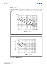
Страница 16: ...racteristic data in order to achieve the required safety level for your plant machine Operating Mode EN ISO 13849 1 2015 PL EN ISO 13849 1 2015 Category EN 62061 SIL CL EN 62061 PFHD 1 h IEC 61511 SIL IEC 61511 PFD EN ISO 13849 1 2015 TM year PL e Cat 4 SIL CL 3 2 31E 09 SIL 3 2 03E 06 20 All the units used within a safety function must be considered when calculating the safety characteristic data...

Страница 17: ...tching frequency and the load on the relay output If the service life graphs are not accessible the stated PFH value can be used irrespective of the switching frequency and the load as the PFH value already considers the relay s B10d value as well as the failure rates of the other components ...

Страница 18: ...the number of cycles from which failures due to wear must be expected The wear is mainly caused by the electrical load the mechanical load is negli gible Cycles x 1000 Switching current A Fig Service life graphs at 24 VDC and 230 VAC Number of cycles x 1000 Switching current A Fig Service life graphs at 110 VDC ...

Страница 19: ...o increase the service life sufficient spark suppression must be provided on all relay con tacts With capacitive loads any power surges that occur must be noted With DC contact ors use flywheel diodes for spark suppression Remove plug in terminals Procedure Insert the screwdriver into the housing recess behind the terminal and lever the terminal out Do not remove the terminals by pulling the cable...

Страница 20: ...eclaración descrita anteriormente es conforme con la legislación de armonización pertinente de la Unión L objet de la déclaration décrit ci dessus est conforme à la législation d harmonisation de l Union applicable Der oben beschriebene Gegenstand der Erklärung erfüllt die einschlägigen Harmonisierungsrechtsvorschriften der Union Het hierboven beschreven voorwerp is in overeenstemming de desbetref...

Страница 21: ...logic S r l Via S Vitalino 13 40012 Calderara di Reno Bologna Italy Tel 39 051 6765611 Fax 39 051 6759324 www datalogic com 826002433 Rev C Back cover This document is a translation of the original document ...

Отзывы: