QLM500 INSTALLATION MANUAL
6
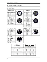
ELECTRICAL CONNECTIONS
CONNECTORS
PWR-IN (Power In)
M12 5P Male
(A-coded)
ID-NET (Out)
M12 5P Female
(A-coded)
Pin Function
Pin
Function
1 Vdc
1 Shield
2 nc
2 Vdc
3 GND
3 GND
4 nc
4 ID+
5 nc
5 ID-
TRG (Trigger)
M12 4P Female
(A-coded)
I/O
M12 8P Female
(A-coded)
Pin Function
Pin
Function
1
+V (I/O)
1
+V (I/O)
2 nc
2 -V
(I/O)
3
-V (I/O)
3
I2+ (input)
4 I1+
(trigger)
4 nc
5 O1+
(output)
6 O1-
(output)
7 O2+
(output)
8 O2-
(output)
ETH1 (Ethernet Port 1)
M12 4P Female
(D-coded)
ETH2 (Ethernet Port 2)
M12 4P Female
(D-coded)
Pin Function
Pin
Function
1 TX+
1 TX+
2 RX+
2 RX+
3 TX-
3 TX-
4 RX-
4 RX-
AUX
M12 5P Female
(B-coded)
Pin Function
1 nc
2 RXA
3 GND
4 TXA
5 nc
Reader
25P D-Sub Female
1
14
25
13
Pin Function
Pin
Function
Pin
Function
1, shell,
Reader Chassis
2 TXM
10
I2B
18
I1A
3 RXM
11
O2+ 19
GND
4 RTSM
12
O2- 20
RXA
5 CTSM
13
Vdc 21
TXA
6 I2A
14
nc
22
O1-
7 GND
15
nc
23
ID+
8 O1+
16
nc
24
ID-
9 nc
17
nc
25
GND
2
1
4
3
5
1
2
3
4
5
2
3
4
1
1
2
3
4
2
3
4
1
5
2
4
6
1
5
8
3
7
2
3
4
1


