background image


MATRIX-1000™ QUICK GUIDE


8


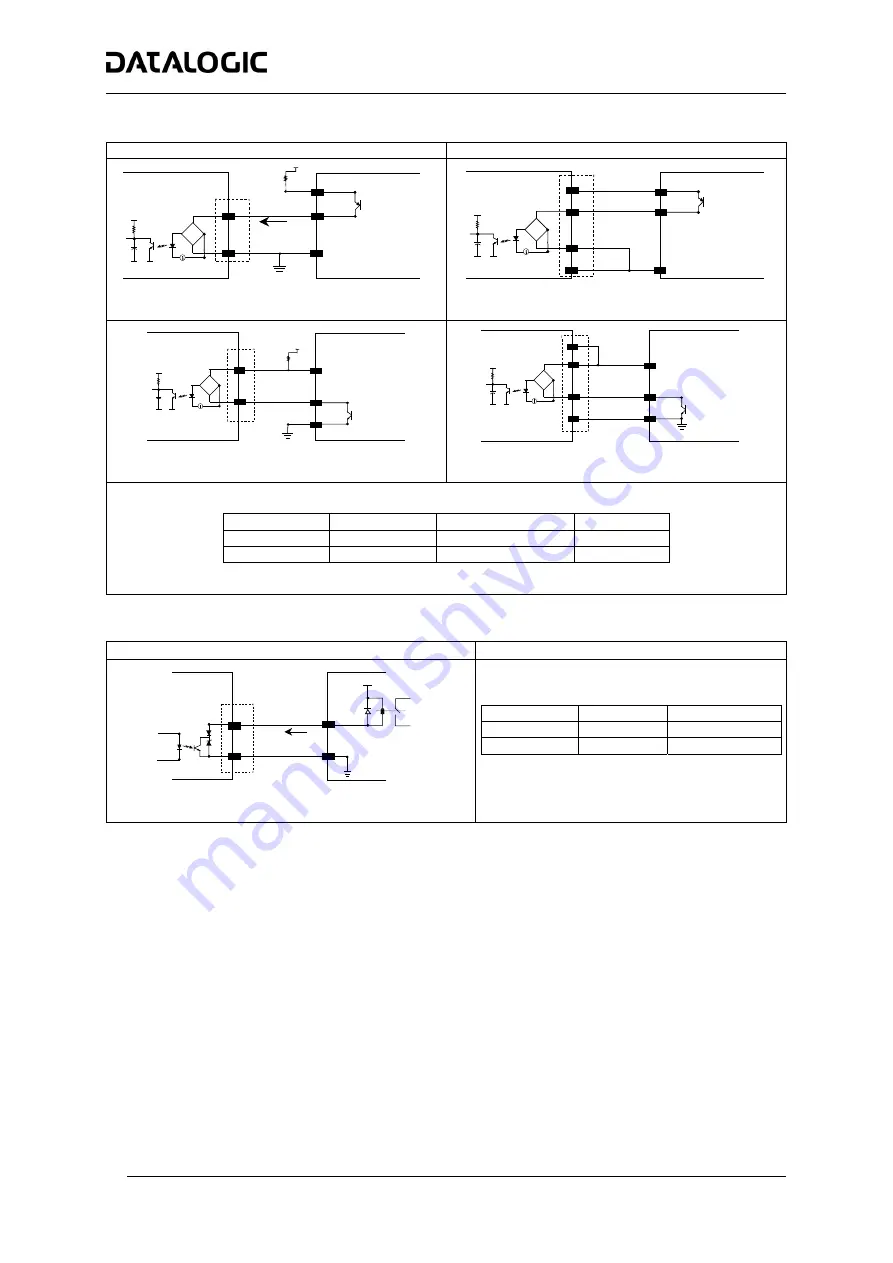
Input / Output Connections: 


Input  

USER INTERFACE 

OUT 

MATRIX 

V

CC


Vext 

GND 

V

~


~

+


-


in


30 Vdc Max. 


Input PNP command using external power


USER INTERFACE 

MATRIX

V

CC

A

B

V

~

~

+

-

25

OUT 

GND 

GND

VS


Input PNP command using Matrix-1000

 power


USER INTERFACE 

VS 

MATRIX 

Vext 

V

V

CC


~

~


+

-

GND 

OUT 

30 Vdc Max. 


Input NPN command using external power


USER INTERFACE 

VS

MATRIX

A

B

GND

V

V

CC

~

~

+

-

GND


9

OUT 

25 


Input NPN command using Matrix-1000

 power


The electrical features of the input are: 
 

INPUT | 

AB 

| Min. 

| V 

AB 

| Max. 

IN

 Max

.


Open 

0 V 

2 V 

0 mA 

Closed 

4.5 V 

30 V 

10 mA 


Output  

MATRIX

USER INTERFACE

Vext

30 Vdc max

+

-

Load

Out


Open collector output connection 


The electrical features of the output are the 
following: 
 

OUTPUT I

Load


V

Out


Open 

0 mA 

30 Vdc Max 

Closed 

10 mA 

1.8 Vdc Max 

 
P

D

 = V

out  

×

 I

load

  = 170 mW Max.


Содержание Matrix-1021 HD

Страница 1: ...Matrix 1000 QUICK REFERENCE GUIDE...

Страница 2: ...sted Computer which supplies power directly to the reader or a UL Listed Direct Plug in Power Unit marked LPS or Class 2 rated 10 to 30 V minimum 1 A In order to meet the EMC requirements connect read...

Страница 3: ...28 Code 93 Code 39 Standard and Full ASCII Interleaved 2 of 5 EAN 8 13 UPC A E including Addon 2 and Addon 5 2 D Data Matrix ECC 200 QR Code POSTAL Australia Post PLANET Royal Mail 4 State Customer PO...

Страница 4: ...nt conditions Test chart provided with the reader Still code at the center of the FOV Code symbology Data Matrix ECC 200 Code resolution Typ 2D Code Resolution Tilt angle 45 Pitch angle 15 Decode mode...

Страница 5: ...cted 11 12 NC Not connected 16 OUT 3 Configurable digital output 3 positive pin 17 OUT 3 Configurable digital output 3 negative pin 18 EXT_TRIG A External trigger polarity insensitive 19 EXT_TRIG B Ex...

Страница 6: ...8 CTS 5 CTS How To Build A Simple Interface Test Cable The following wiring diagram shows a simple test cable including power external push button trigger and PC RS232 COM port connections 25 pin D su...

Страница 7: ...X 100 C BOX 100 Terminal Block Connectors Power 1 3 5 VS 2 4 6 GND 7 8 EARTH GROUND 20 40 Reserved Inputs 27 EXT TRIG A polarity insensitive 28 EXT TRIG B polarity insensitive 29 30 NC 31 33 NC 32 34...

Страница 8: ...T 30 Vdc Max Input NPN command using external power USER INTERFACE VS MATRIX A B GND V VCC GND 9 OUT 25 Input NPN command using Matrix 1000 power The electrical features of the input are INPUT V AB Mi...

Страница 9: ...inch M4 x 5 n 4 18 1 0 71 4 0 16 73 2 87 57 2 24 28 1 1 11 57 2 24 121 4 76 57 2 24 M4 x 5 n 4 57 2 24 Overall Dimensions 73 2 87 4 2 0 17 15 0 59 37 1 46 4 2 0 17 95 3 74 47 5 1 87 8 2 0 3 2 47 5 1 8...

Страница 10: ...0 C BOX 100 C BOX 100 C BOX 100 Power Host e e e d d d c c Multidrop Network Main Interface d Auxiliary Interface Local Echo e External Trigger 0 31 1 Matrix 1000 c Auxiliary Interface Local Echo d Ex...

Страница 11: ...to electromagnetic compatibility and product safety Bas e sur la l gislation des Etates membres relative la compatibilit lectromagn tique et la s curit des produits ber die Ann herung der Gesetze der...

Отзывы: