background image

INSTALLATION GUIDE   V

PREFACE

ABOUT THIS MANUAL

This Installation Guide is provided for users seeking advanced technical information, including 
connection, programming, maintenance and specifications. The Product Reference Guide and


other publications associated with this product can be downloaded free of charge from the web-
site listed on the back cover of this document.

Manual Conventions

The following conventions are used in this document:

The symbols listed below are used in this manual to notify the reader of key issues or procedures 
that must be observed when using the reader:

NOTE

TECHNICAL SUPPORT

Support Through the Website

Datalogic provides several services as well as technical support through its website. Log on
to (www.datalogic.com).

For quick access, from the home page click on the search icon

, and type in the name of the


product you’re looking for. This allows you access to download Data Sheets, Manuals, Soft-
ware & Utilities, and Drawings.

Hover over the Support & Service menu for access to Services and Technical Support.

Reseller Technical Support

An excellent source for technical assistance and information is an authorized Datalogic 
reseller. A reseller is acquainted with specific types of businesses, application software, and


computer systems and can provide individualized assistance.

Notes contain information necessary for properly diagnosing, repairing and 
operating the reader. 

CAUTION

The CAUTION symbol advises you of actions that could damage equipment 
or property.

WARNING

The WARNING symbol advises you of actions that could result in harm or 
injury to the person performing the task.

Содержание 938100001

Страница 1: ...STS320 INSTALLATION GUIDE Solution for Tires Sorting ...

Страница 2: ...documentation Electronic versions of this document may be downloaded from the Datalogic website www datalogic com If you visit our website and would like to make comments or suggestions about this or other Datalogic pub lications please let us know via the Contact page Disclaimer Datalogic has taken reasonable measures to provide information in this manual that is complete and accu rate however Da...

Страница 3: ...unting 5 Presence Sensor Positioning 7 ELECTRICAL CONNECTIONS 9 STS320 Wiring Diagram 9 Power Supply 10 M12 X Coded 8 Pin Connector Ethernet 10 Digital Inputs 11 Input Connections for Presence Sensors provided in the package 12 Input Connections from PLC 13 Digital Outputs 14 Output Connections Using STS320 Power 15 SOFTWARE CONFIGURATION 16 STS320 Default Configuration 16 Configuration using Web ...

Страница 4: ...CONTENTS iv STS320 Quick Start 23 Ethernet Device Discovery 23 Device Configuration 24 Backup and Restore Through DL CODE 25 Backup 25 Restore 26 Replacement 26 TROUBLESHOOTING 27 General Guidelines 27 ...

Страница 5: ...rough its website Log on to www datalogic com For quick access from the home page click on the search icon and type in the name of the product you re looking for This allows you access to download Data Sheets Manuals Soft ware Utilities and Drawings Hover over the Support Service menu for access to Services and Technical Support Reseller Technical Support An excellent source for technical assistan...

Страница 6: ...ed in the applicable European directive Since the directives and applicable standards are subject to continuous updates and since Datalogic promptly adopts these updates therefore the EU declaration of conformity is a living document The EU declaration of conformity is available for competent authorities and customers through Datalogic commercial reference contacts Since April 20th 2016 the main E...

Страница 7: ...ommand The following warning label content is applied to the laser equipped products indicated in the General View illustration of this document Example Laser Warning Labels The package includes labels for countries where the warning text in other languages is mandatory Put them on the product instead of the English version To be applied on the mounting bracket To be applied on each Matrix 320 ATS...

Страница 8: ... also a precision product and therefore before and during installation it must be handled correctly to avoid damage avoid that the array is dropped do not fine tune the positioning by striking the array do not weld the array into position which can cause electrostatic heat or reading window damage do not spray paint near the array which can cause reading window damage ...

Страница 9: ... GUIDE IX GENERAL VIEW Figure 1 STS320 14 LEDs illuminator 1 5 3 2 4 6 6 Figure 2 STS320 36 LEDs illuminator 1 ID NET Master 4 Positioning Slot 2 ID NET Slaves 5 Reading Windows 3 Mounting Slots 6 Laser Class and Warning Labels ...

Страница 10: ...X STS320 ...

Страница 11: ...and all the parts supplied with the equipment are present and intact when opening the packaging The list of parts includes STS320 array Matrix 320 ATS xxx readers mounting bracket 2x MEP 593 PHOTOCELL KITS 93ACC1791 CAB ETH X M05 M12 IP67 GETH X CAB 5M 93A050124 CAB DS03 S M12 IP67 TO CBX 3M 93A050059 CBL 1480 05 M12 5P MALE FEMALE 5M IDNET 93A050051 SCREW M 8 x 25 HAMMER HEAD INOX NUT Special Sup...

Страница 12: ...SORT 3_HEAD HI RES 938100004 3 1 A max STS320 014 TIRE SORT 4_HEAD HI RES 938100005 4 1 A max STS320 015 TIRE SORT 5_HEAD HI RES 938100006 5 1 A max STS320 016 TIRE SORT 6_HEAD HI RES 938100007 6 0 A max Top Reading Commercial Vehicle Solution STS320 103 TIRE SORT 3_HEAD ST RES LR 938100008 3 1 A max STS320 104 TIRE SORT 4_HEAD ST RES LR 938100009 4 1 A max STS320 113 TIRE SORT 3_HEAD HI RES LR 93...

Страница 13: ...013 3 0 25 10 650 25 59 620 24 41 870 34 25 730 28 74 152 5 98 STS320 014 4 850 33 46 STS320 015 5 1050 41 34 STS320 016 6 1250 49 21 STS320 103 3 0 35 14 950 37 4 400 15 75 850 33 46 1250 49 21 1000 39 37 211 8 31 STS320 104 4 1250 49 21 STS320 113 3 0 25 10 650 25 59 830 32 68 1230 48 43 970 38 19 145 5 71 STS320 114 4 850 33 46 STS320 115 5 1050 41 34 STS320 116 6 1250 49 21 STS320 203 3 0 30 1...

Страница 14: ...INSTALLATION 4 STS320 Figure 3 STS320 14 LEDs illuminators mounting distance Figure 4 STS320 36 LEDs illuminators mounting distance ...

Страница 15: ...has to be coupled to the frame with the M8 x 25 mm T bolt Figure 6 STS320 Plate Support Assembly Mount the plate support assembly onto the bottom side of the STS320 supporting frame When the T bolt is inserted into the profile slot position it directly over the cen ter1 of the conveyor and completely tighten the nut Finally the STS320 can be mounted onto the station frame 1 For STS320 models with ...

Страница 16: ...t assembly and the supporting profile until it reaches the end The plate support assembly can fully support the STS320 weight without human help Fix the STS320 using 4 T bolts and nuts not supplied to the supporting profile When the main plate slot is fully inserted onto the plate support assembly the 4 mounting slots are aligned with the supporting profile groove Also screw the locknut onto the p...

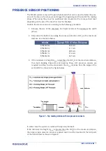
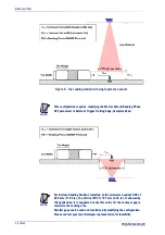
Страница 17: ...eyor direction FOVv at the maximum distance See the table below STS320 00x 260 mm STS320 01x 211 mm STS320 10x 305 mm STS320 11x 214 mm STS320 20x 247 mm 3 If the minimum tire height Hmin is less than the FOVv 2 at the maximum distance then both Reading Phase ON and Reading Phase OFF presence sensors are required and they must be mounted at the Hmin distance from the edges of the vertical FOV as s...

Страница 18: ...railing Edge Complete Read For Bottom Reading Stations installed at the minimum nominal DOF of 280 mm 11 02 in the Vertical FOV is 157 mm 6 18 in If allowed by the application it is suggested to use this value for the conveyor gap to maximize the reading area Smaller gaps can be used and maximized by modifying the configuration Please contact your local Datalogic representative for feasibility ...

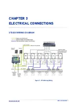
Страница 19: ...INSTALLATION GUIDE 9 CHAPTER 3 ELECTRICAL CONNECTIONS STS320 WIRING DIAGRAM Figure 9 STS320 Array Wiring ...

Страница 20: ...nstallation Manual for details M12 X CODED 8 PIN CONNECTOR ETHERNET The Host can connect to the STS320 Master reader s on board Ethernet M12 X Coded connector This interface is IEEE 802 3 10 BaseT and IEEE 802 3u 100 BaseTx compliant Figure 11 M12 X Coded Female Ethernet Network Connector M12 X Coded Ethernet Network Connector pinout Pin Name Function 1 2 3 4 5 6 7 8 DA DA DB DB DD DD DC DC Bidire...

Страница 21: ...2 Leading Edge External Trigger Trailing Edge or Input 2 Trailing Edge NOTE The electrical features of both inputs are VAB 30 Vdc max IIN 10 mA reader 12 mA CBX max The active state of these inputs is selected in software An anti disturbance filter is implemented in software on both inputs so that the mini mum pulse duration is 0 5 milliseconds This value can be increased through software These in...

Страница 22: ...r 1 CBX500 Row 2 Function brown black blue V I1A I1B V bridge to I1B Power Source External Trigger External Trigger A polarity insensitive External Trigger B polarity insensitive Power Reference External Trigger Figure 12 Presence Sensor connected to External Trigger The yellow Trigger LED on the reader is on when the active state of the External Trigger corresponds to ON Power is available direct...

Страница 23: ...ION GUIDE 13 Figure 13 Presence Sensor Connected to Input 2 Input Connections from PLC Alternatively the reading system can be controlled by a digital output of a PLC For this purpose connect the switched signal and the appropriate reference level as shown in the figures below PLC Signal CBX500 Row 2 Function Input Reference I1A I1B External Trigger A polarity insensitive External Trigger B polari...

Страница 24: ...are opto coupled The mean ing of the three outputs can be defined by the user They are typically used to signal the data collection result They are also available to the Host either serial or Fieldbus to be driven independently The electrical features of the two outputs are the following VOUT ILOAD 0 mA max 24 Vdc VOUT ILOAD 100 mA max 3 Vdc ILOAD max 100 mA By default Output 1 is associated with ...

Страница 25: ...n then manage larger power consuming devices such as signaling lights or other machinery CBX500 Function V 01 O1 O2 O2 V Power Source Outputs Output 1 Output 1 Output 2 Output 2 Power Reference Outputs Figure 16 Open Emitter Output using STS320 Power Figure 17 Open Collector Output using STS320 Power CAUTION Power is available directly to the Output Device independently of the Power Supply Switch ...

Страница 26: ... as well as to a file STS320 DEFAULT CONFIGURATION Default IP Address 192 168 3 100 Code symbologies CODE128 CODE39 INT2OF5 min 8 digits Layout type Synchronized Operating mode Phase mode Phase ON Input 1 Leading Edge Phase OFF Input 2 Trailing Edge Acquisition trigger Periodic 25 ms Data collection type Code combination 1 expected code Output Good Read Output 2 Green Spot 360 Green Feedback No Re...

Страница 27: ... Web Monitor page of the selected device Display and configure the Ethernet settings as shown in the figures below left device in DHCP modea a Use DHCP addressing only if the network is connected to a DHCP Server right device in Static mode Set the device description In case of Slave devices this button is only available if the corresponding Master device is reachable At least one device must be r...

Страница 28: ... Code Setting View Extended enters Extended menu Extended Exit returns to Main menu Backup Yes performs Backup uninterruptible No returns to Extended menu Restore Yes performs Restore uninterruptible No returns to Extended menu NOTE Backup procedure 1 Make sure the Write Protection switch inside the CBX500 on the BM100 is unlocked 2 Select the Backup item from the Extended menu and press the Enter...

Страница 29: ... browser by inputting the IP address of the reader STS320 must be available on the LAN This works on major browsers also on smartphones and tablets which support HTML5 Chrome Firefox Edge IE Safari iOS Android IE Mobile latest latest 14 11 10 10 Nougat 7 0 Marshmallow 6 0 11 13 10 9 9 Lollipop 5 0 5 1 9 8 8 KitKat 4 4 7 7 Jelly Bean 4 1 4 2 4 3 The Web Monitor tool provides the following features ...

Страница 30: ...Wed Jan 23 2019 jpg The options button opens an options panel on the Monitoring window which allows setting the quality of the image to monitor higher quality images reduce framerate showing only positive results good read only negative results or all results showing Code List showing Web Monitor images per second showing x y Coordinates to the Monitoring window The coordinates report the mouse po...

Страница 31: ...aders and arranged side by side in a single frame The Mosaic view provides two main operating modes Live and Pause It is possible to switch between both modes using the button at the bottom left of the page In Live Mode the page is automatically updated at the end of each reading phase The phase result is shown by a colored box around the entire frame green for Good Read red for No Read yellow for...

Страница 32: ...ion soft ware To install and run DL CODE you should have a Laptop or PC that meets or exceeds the following 2 00 GHz or faster microprocessor Windows 7 8 1 or 10 1 GB RAM 2 GB hard disk for 64 bit machines 1 GB hard disk for 32 bit machines 100 Base T Ethernet One 19 or larger monitor optimized for 1280x1024 resolution The Mosaic view is intended to be a real time monitoring tool If the con nectio...

Страница 33: ...very feature to accomplish this task The discovery feature will also show devices not belonging to the LAN and display them in gray The following procedure will demonstrate an example configuration 1 First the device must be added to the LAN by aligning its IP Address to the net work The network administrator should provide valid LAN address es 2 Click on the device wrench icon to open the Device ...

Страница 34: ...cquisition default Phase mode A Fieldbus communication channel can be selected under this section Good Read Setup this group manages data collection default Code Combina tion 3 Output Data Formatting this group manages the output message to the Host The Image Saving function can be enabled and managed under this section Output Setup this group manages the digital outputs as well as the Green Red S...

Страница 35: ... CODE Device menu select Backup to external stor age device and follow the procedure then perform a backup selecting Backup current Internal Network configurations to a file on PC and follow the procedure NOTE After performing the Backup installation is completed You can check the station perfor mance using the DL CODE Monitor or the Web Monitor CAUTION For Master Slave networks any other configur...

Страница 36: ... mounting the fast bracket on the new device and fixing it to the array mounting bracket making sure it is aligned screws fully seated into the end of the fast bracket slots Refer to the Product Reference Guide for more details 2 Connect the new device make sure the new device has been previously set to fac tory default 3 Run the Restore procedure by selecting Restore from external storage device ...

Страница 37: ...ould be lit If a yellow LED is lit together with the green one please check the mechanical position and orientation of the sensor and reflector Every time the yellow LED on the sensor is lit the corresponding LED in the CBX500 connection box must be lit For Trigger this must be the yellow LED and for the Input 2 the green one If this is not the case please check the wiring of the sensors No Presen...

Страница 38: ...ase please replace the reader and send it to repair Do the readers read codes Place a correctly positioned code under each reader If the reader has read the code the GOOD read green LED must light up A green spot must also light up on the code surface If this is not the case please replace the reader and send it to repair Troubleshooting Guide for STS320 Solutions Problem Suggestion ...

Страница 39: ......

Страница 40: ...ht no part of this documentation may be reproduced stored in or introduced into a retrieval system or transmitted in any form or by any means or for any purpose without the express written permission of Datalogic S p A and or its affiliates Datalogic and the Datalogic logo are registered trade marks of Datalogic S p A in many countries including the U S and the E U www datalogic com 821006920 Rev ...

Отзывы: