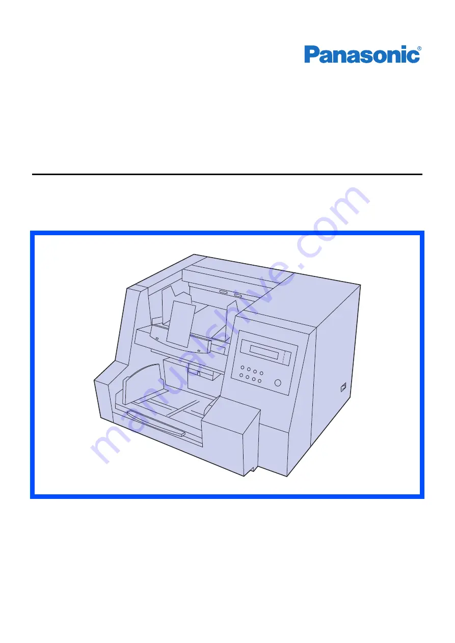
background image

High speed Scanner

Model No. KV-S3085

This manual contains information on installing the scanner. Please read this manual before
operating unit.
For information on operating the scanner, please read the operating instructions recorded on the
CD-ROM enclosed with this unit.
For information on maintaining the scanner, please read the maintenance manual enclosed with
this unit.

Please carefully read this manual, the operating instructions and maintenance manual.
Keep these documents in a safe place for future reference.

Installation Manual

High Speed Color Scanner

Model No. KV-S3105C

Summary of Contents for KV-S3085

Page 1: ...se read the operating instructions recorded on the CD ROM enclosed with this unit For information on maintaining the scanner please read the maintenance manual enclosed with this unit Please carefully read this manual the operating instructions and maintenance manual Keep these documents in a safe place for future reference Installation Manual High Speed Color Scanner Model No KV S3105C ...

Page 2: ...ncy ENERGY STAR and the ENERGY STAR certification mark are registered US marks Microsoft Windows and Windows NT are either registered trademarks or trademarks of Microsoft Corporation in the United States and or other countries ISIS is a registered trademark of Pixel Translations a division of Captiva Software Corporation Adobe Acrobat and Reader are registered trademarks of Adobe Systems Incorpor...

Page 3: ...nts 13 Power turn on sequence 14 About the language setting 14 About LED 15 Drivers and Utilities CD ROM 16 Contents of this CD ROM 16 Install device driver Except Windows NT 4 0 17 Install the TWAIN ISIS driver 17 Install RTIV 17 Install the Multi Color Dropout Utility 18 View manuals 18 Uninstalling the device driver 18 Increasing the Memory 19 DIMM module extension 19 Installing optional memory...

Page 4: ...ld be used only with a power cord that is supplied by the manufacturer Power Source WARNING 220 240 V equipment A certified power supply cord has to be used with this equipment The relevant national installation and or equipment regulations shall be considered A certified power supply cord not lighter than ordinary polyvinyl chloride flexible cord according to IEC 60227 designation H05VV F 3G 1 0 ...

Page 5: ...vere electrical shock if the cut off plug is inserted into any 13 amp socket If a new plug is to be fitted please observe the wiring code as shown below If in any doubt please consult a qualified electrician WARNING This appliance must be earthed IMPORTANT The wires in this mains lead are coloured in accordance with the following code Green and Yellow Earth Blue Neutral Brown Live As the colours o...

Page 6: ...Notice 6 Caution Labels 注意 ローラーに手を触れないでください 指を巻き込まれてけがの原因になります ...

Page 7: ...r items on the unit Do not place the unit in an area where there is a lot of smoke dust chemical fumes or vibration Do not leave the power cord plugged into the AC outlet if the unit will not be used for an extended period Do not place the unit on an uneven or unstable surface Do not disassemble the unit This will void your warranty Stop operation immediately if the unit emits smoke excessive heat...

Page 8: ... operate or place the unit in a vertical position Do not place the unit near a heating appliance or an air conditioning vent Do not place the unit in a room with extremely high or low humidity Do not place the unit near other appliances which gen erate large electrical noise Do not place the unit on a carpet Static electricity can cause the unit to malfunction Do not drink or inhale the included r...

Page 9: ...surface of the disc Do not leave the disc out of its protective case Do not leave the disc in direct sunlight or near heat sources Do not place heavy objects on the disc case or drop the case To clean the disc hold the disc by its edges and wipe it from the center to the edges with a dry soft cloth ...

Page 10: ...ents for proper ventilation CD ROM 1 piece Operating Instructions Driver Software Power Cord Installation manual Maintenance manual Roller cleaning paper 3 pieces Shading paper Blower Spacer Exit tray stopper Exit stopper Pallet Plastic band Be sure to use a power cord whose shape matches the shape of the electric outlet USB cable Clearance needed to open back door 350 mm 13 8 Clearance needed to ...

Page 11: ...opper metal guides slightly together and insert them into the stopper slots of the exit tray Then pull up the plastic part of exit tray stopper Install the exit tray stopper in the sequence of 1 through 3 When using short paper put the exit stopper on the exit tray Stopper slots Exit tray stopper Exit stopper ...

Page 12: ...ned locally Set the power switch on the scanner and on the host computer to OFF before connecting the interface cable If a problem occurs refer to Troubleshooting in the Operating Instructions CD ROM USB Connection Caution Use only with the power cord that is supplied by manufacturer Use the USB cable provided with the unit Household AC outlet AC 100 120 V 50 60 Hz AC 220 240 V 50 60 Hz Power cord...

Page 13: ...plication Windows NT 4 0 does not support USB interface For Windows NT 4 0 you must install the ASPI layer software that the SCSI board vender provides Use USB 2 0 interface because scanning speed of USB 1 1 interface is slow If you connect the scanner to a USB hub it is not guaranteed to work When using the scanner with other SCSI devices connected by daisy chain connection it is not guaranteed t...

Page 14: ...n the unit s power is turned on for the first time after the unit was purchased English is the default language 1 Turn the power on while pressing the HOME key When High Speed Scanner or other words appear on the LCD release the HOME key 2 Use the 2 key or the 1key to select English Letter English A4 Deutsch A4 or 3 Press the HOME key The display will change to the selected language then the scann...

Page 15: ... to be cleaned or replaced Refer to Maintenance Manual or Operating Instructions CD ROM for the way of cleaning or replacing the rollers LED light Status Green Ready to scan or scanning Green flashing Sleep mode Orange Initializing or warning Orange flashing Sleeping with warning 1 Red An error occurred ...

Page 16: ... PDF files on the Drivers Utilities CD ROM provided with the scanner For use print the control sheets in the same size as the document pages to be scanned Refer to Section 3 35 Detect Con trol Sheet of the PIE Reference Manual Contents Quick menu Applicable user Driver install Device Driver Windows 98 Windows Me Windows 2000 Windows XP user TWAIN TWAIN application user ISIS ISIS application user A...

Page 17: ...on Install the TWAIN ISIS driver 1 Insert the CD ROM in your computer 2 Quick menu software runs automatically 3 Select your scanner 4 Select TWAIN driver or ISIS driver 5 Follow the instructions on the screen Install RTIV 1 Insert the CD ROM in your computer 2 Quick menu software runs automatically 3 Select your scanner 4 Select RTIV 5 Follow the instructions on the screen Even if the screen Digi...

Page 18: ...are runs automatically 3 Select your scanner 4 Select a manual from the list 5 You can view the manual using Adobe Reader Uninstalling the device driver 1 Use Control Panel Add Remove Programs In Windows XP select Add or Remove Programs 2 Select Panasonic High Speed Scanner Device Driver and click Change Remove 3 Follow the instructions on the screen In case of uninstalling TWAIN ISIS RTIV Multi C...

Page 19: ...y module DIMM Nonbuffered Single 3 3V 0 3V power supply Frequency CAS Latency 100MHz CL 2 133MHz CL 2 133MHz CL 3 64MB 128MB 256MB or 512MB may be used Reference DIMM module which has been evaluated and approved for use with this scanner EDGE 128MB Module EDGE 256MB Module EDGE 512MB Module Kingston 128MB Module Kingston 256MB Module Kingston 512MB Module Installing optional memory DIMM module Ins...

Page 20: ...Injury may result Installing the DIMM module Insert the DIMM module into the connector on the interface board 1 then push it until it clicks into place NOTE Be sure that the module notch is to the left side or the DIMM module will not be in the proper position To remove the DIMM module pull the tabs at both sides of the connector Do not touch any electrical components on the surface of the board t...

Page 21: ...nterface board 1 Insert the interface board into the unit along the rails and push it in firmly Confirm that the interface board plate is fully inserted until it firmly locks in place 2 Secure the interface board with the four screws Rail Rail ...

Page 22: ...riginal scanner carton packing materials 1 Disconnect your scanner from the electrical outlet and the interface cable 2 Remove the exit stopper and exit tray stopper from the scanner 3 Pack the scanner To avoid damage due to the weight of the unit the unit should be shipped with the pallet tightened by the plastic bands CD ROM 1 piece Operating Instructions Driver Software Power Cord Installation ...

Page 23: ...orporation of North America Two Panasonic Way Secaucus New Jersey 07094 Panasonic Canada Inc 5770 Ambler Drive Mississauga Ontario L4W 2T3 Matsushita Electric Industrial Co Ltd http www panasonic co jp global 2005 Panasonic Communications Co Ltd All Rights Reserved ...

Reviews: