DM4170 – Installation Manual
Installing the DM4170
204.4308.03
12
LED PWR
•
GREEN ON: Indicates that the source is powering the switch.
•
OFF: Power source failure or not powering.
LED
ALARM/FAIL
•
OFF: Equipment operating normally, no failures or alarms detected.
•
YELLOW/AMBER ON: Indicates that alarms were detected by the
equipment.
•
RED ON: Indicates that the equipment is in internal failure state.
When the power is connected to the equipment, this LED will turn red for a
short time, and then will turn off.
Table 5 - Status LED Behavior
S
ERIAL CONSOLE INTERFACE
(RS-232)
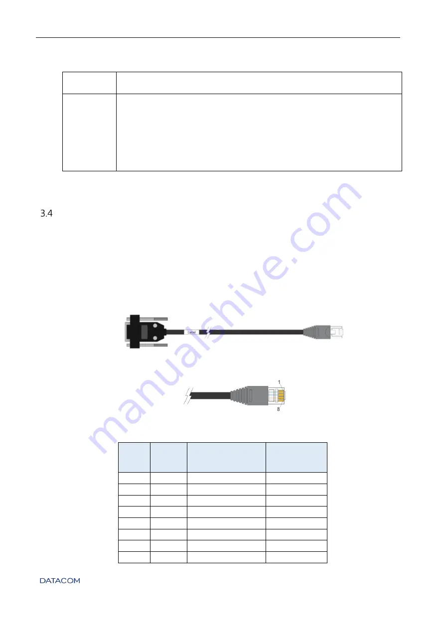
The DM4170 switch has a console port for local management. The console port uses an RJ45
connector. A cable with a male RJ45 connector and a female DB9 connector must be used for
the connection to a computer or laptop.
The serial console cable is an accessory included in the DM4170. Additional cables can be
purchased separately via code 710.0137.xx or assembled as described in the following
images. The pin assignment of the RJ45 connector and its match with the DB9 connector is
described in
ONSOLE INTERFACE CONNECTOR PIN ASSIGNMENT
Figure 5 - Console cable
Figure 6 - RJ45 console cable connector pins
RJ45
Male
DB9
Female
Function
DM4170 Input
/ Output
1
-
Reserved
-
2
-
Reserved
-
3
2
RS232_TX
Output
4
5
DGND
Ground
5
5
DGND
Ground
6
3
RS232_RX
Input
7
-
Reserved
-
8
-
Reserved
-


