


DM-
SV01 ● Product Manual ● Rev. 1.1
25
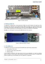
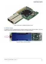
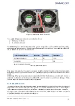
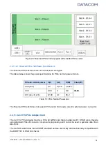
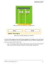
Figure 21: DM-SV01 power connector
The signals of the power connector are defined as below:
● RED wire : +12V DC
● BLACK wire: Ground
The DM-SV01 power demand depends on the system configuration, such as CPU types and quantity,
memory speed and quantity, E1.S SSDs quantity, additional PCIe cards, etc. The maximum power that
can be delivered is shown in the table below.
Power Requirements
Minimum
Nominal
Maximum
DC Input Voltage (V)
10.4
12
13.9
Current (A)
--
*
60
* Depends on system configuration
Table 10: DM-SV01 Power
If the power demanded by the system exceeds a predefined safety threshold, a throttling mechanism
will be triggered, forcing the CPUs to lower their operating frequency in order to decrease overall system
power.
Additionally, if the system power exceeds a predefined critical threshold (e.g. a board short circuit), a
protection mechanism will shutdown the DM-SV01 power in order to avoid board damage. If this
situation happens, Datacom support must be contacted.
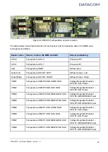
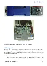
2.2.10 DM-SV01 Sensors
The DM-SV01 server has a set of sensors which are responsible for monitoring the voltage, current and
temperature at several relevant spots of the system. The sensors information is used for controlling the
FANs speed and generating alarms or emergency shutdown in case of reaching a critical threshold.
The figure below shows the location of the temperature sensors, which can have its values visualized
by means of the BMC web management interface.


