background image

6  

  Cable Installation 

Datacolor 245™ User's Guide 

Communications Cable 

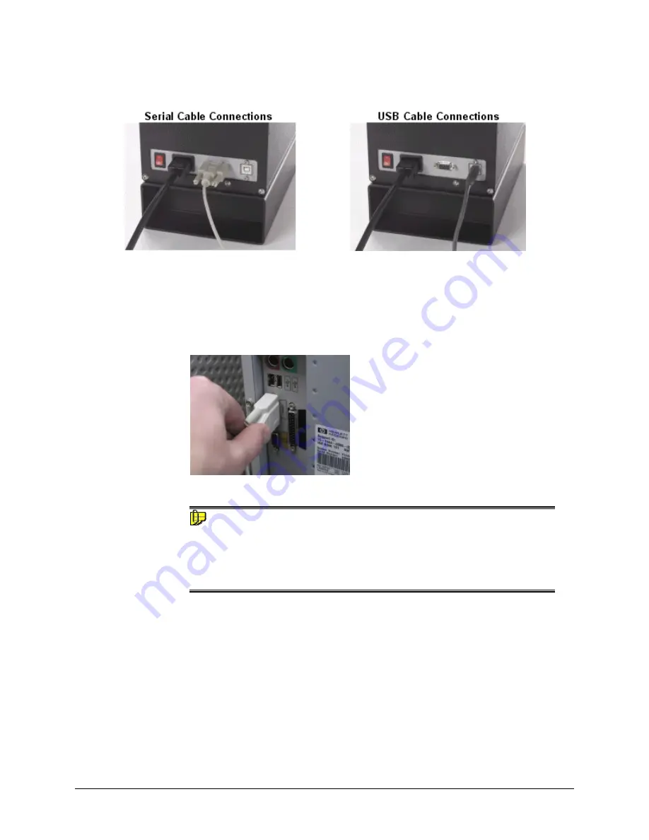
The instrument is connected to a computer through either a serial port or USB port: 


1.  Plug the female end of the power cord into the power receptacle on the rear 

panel of the instrument.  Insert the plug into a standard AC outlet. 

2.  Connect the male connector on the instrument cable to the appropriate female 

connector on the rear panel of the instrument. 

3.  Connect the female connector on the instrument cable to a communications port 

on the back of the computer.  


4.  Tighten each connection securely to ensure proper signal. 

 NOTE 

If there is more than one serial port on the computer, make a note of the port 
being used.  You may need to enter this information into the program.   

See USB Driver Installation in this guide for detailed instructions regarding 
the software installation.  See the Appendix for a description of the RS-232C 
connector pin assignments. 

Содержание 245

Страница 1: ...Datacolor Datacolor 245 User s Guide ...

Страница 2: ... are incorporated into forthcoming versions Datacolor reserves the right to make improvements and or changes in the product s and or program s described in this material at any time Copyright 2005 Datacolor ALL RIGHTS RESERVED This material may not be reproduced or duplicated in whole or in part without the express written permission of Datacolor Microsoft MS DOS and Microsoft Windows are register...

Страница 3: ...stalling Calibration Data 16 Controls and Indicators 17 Status Panel 17 Powering Up 18 Instrument Calibration 18 Sample Presentation and Measurement 21 About Sample Presentation 21 Sample Viewing Port 22 Maintenance 25 About Instrument Maintenance 25 Tile Handling and Cleaning 25 Handling Tiles 25 Cleaning Tiles 25 Storage 26 Cleaning the Black Trap 26 Appendix 27 Datacolor 245 Optical Block Diagr...

Страница 4: ......

Страница 5: ... improved repeatability and long term stability 45º 0º instruments are used for quality control applications when both color and appearance features are being evaluated The Datacolor 245 includes the following standard features Dual beam measurement using pulsed xenon light source Datacolor proprietary high end sensor Conformance to ASTM E1164 Standard Practice for Obtaining Spectrophotometric Dat...

Страница 6: ...Datacolor instruments that employs state of the art features including the spectrometer light source and optics Below is a summary of those features FEATURE DESCRIPTION PURPOSE BENEFIT Instrument Type Dual beam spectrophotometer with xenon flash lamp Industry standard Measurement Geometry 45º illumination 0º viewing Results provide good agreement with visual evaluations of sample color SP2000 Spec...

Страница 7: ...te tile are used each time the instrument is calibrated The green tile is used to perform an optional diagnostic test Calibration Data The calibration procedure uses white data that must be installed on the system It is data unique for the white calibration tile and is provided on either a diskette or a CD It is included with the instrument accessories NOTE The serial number on the back of the whi...

Страница 8: ...4 Accessories Datacolor 245 User s Guide This page intentionally left blank ...

Страница 9: ...a power cable and either a serial cable or a USB cable to connect the instrument to the computer WARNING Read Electrical and Environmental Requirements section before connecting your instrument The connections for these cables are found on the back of the instrument Power Cable A six foot power cable is provided with the instrument Power is supplied to the back of the unit via a 3 prong male conne...

Страница 10: ...propriate female connector on the rear panel of the instrument 3 Connect the female connector on the instrument cable to a communications port on the back of the computer 4 Tighten each connection securely to ensure proper signal NOTE If there is more than one serial port on the computer make a note of the port being used You may need to enter this information into the program See USB Driver Insta...

Страница 11: ...CD labeled USB Drivers and Documentation into the CD ROM drive 2 Connect the USB cable to the instrument and to the USB port on the computer When this connection is made the system detects a new piece of hardware and the screen below automatically appears The New Hardware Wizard automatically replaces this screen 3 Click Next to continue with the USB driver installation ...

Страница 12: ...ouse A check will appear To remove a check place the cursor over a check and click the mouse The check will disappear When you have completed your selections click Next 5 A default location appears in the Copy manufacturer s files from field If the driver software is in a different location click Browse and identify the correct location If the correct location is identified click OK The program wi...

Страница 13: ...Datacolor 245 User s Guide Cable Installation 9 Click Next The Wizard will begin copying the files to the computer 6 When the copy is complete the window below appears ...

Страница 14: ...ser s Guide 7 Click Finish Do not remove the USB Driver CD from the drive The Wizard will close and then immediately reopen and repeat the procedure You must complete it a second time to successfully copy the file 8 Click Next 9 Click Next ...

Страница 15: ...tion box Then click Next 11 If the CD drive containing the files is displayed click OK If it is not displayed click the Browse button and locate the CD drive on your system 12 Click Next The Wizard will begin copying the files to the computer When the copy is completed the window below appears 13 Click Finish ...

Страница 16: ...u manually assign the port number Refer to the program User s Guide for information to assign edit the instrument port number If you change the USB port you are using for the instrument you must edit the com port assignment in the Datacolor programs The procedure for viewing editing the com port assignment is as follows To view or change the com port assignment for the USB port you must do the fol...

Страница 17: ...Datacolor 245 User s Guide Cable Installation 13 The Systems Properties dialog box displays ...

Страница 18: ... Installation Datacolor 245 User s Guide 4 Click the Hardware Tab 5 Click the Device Manager button The Device Manager window displays 6 Go to the Ports heading Click on the plus to display the port selections ...

Страница 19: ...Datacolor 245 User s Guide Cable Installation 15 7 Click USB Serial Port The USB Serial Port COM3 Properties dialog box displays 8 Click Port Settings The dialog box below appears ...

Страница 20: ... you have completed the changes click OK Changing the COM Port Assignment in Datacolor Programs To enable the USB port for color measurements you may need to change the com port assignment in the applications program Refer to the program documentation for the specific Datacolor applications program you are running for instructions to configure the instrument NOTE If you are installing a new instru...

Страница 21: ...Panel The status panel indicates the current instrument settings being used Below is the status panel for the Datacolor 245 OPTION DESCRIPTION Measuring Instrument is making a measurement Do not remove the sample from the port when this indicator is lit Ready Instrument is ready for use ...

Страница 22: ...ights on the status panel will flash and then the Ready light will stay lit NOTE If the instrument power is not turned on before a Datacolor program is launched you may receive an error message 4 When the Ready light remains on your instrument is ready to use 5 Launch a Datacolor program Instrument Calibration The instrument should be calibrated every 8 hours to compensate for changes in the envir...

Страница 23: ...or calibration vary from one program to another The Datacolor Users Guide for the program you are running provides step by step instructions regarding the software setup and instrument calibration procedure NOTE It is recommended that you calibrate the instrument every 8 hours ...

Страница 24: ...20 Controls and Indicators Datacolor 245 User s Guide This page intentionally left blank ...

Страница 25: ...tention to the positioning of the sample to insure an accurate measurement When positioned correctly the sample rests between the sample holder and the front panel door The sample must completely cover the aperture opening 1 Grasp the sample holder and pull forward 2 Position the sample at the port The sample should completely cover the port opening ...

Страница 26: ...mal operating position WARNING Do not allow sample arm to spring back Sample Viewing Port When measuring small samples you may need to check that the sample is properly positioned at the port To verify that the correct area of the sample is being measured 1 Grasp the tab above the aperture plate ...

Страница 27: ... position The backside of this door reveals the area of the sample covering the port opening 3 If necessary adjust the placement of the sample to target the portion of the sample to be measured The sample must completely cover the port opening 4 Push the door back to its normal position and start the measurement ...

Страница 28: ...24 Sample Presentation and Measurement Datacolor 245 User s Guide This page intentionally left blank ...

Страница 29: ...s grasp the tile using its edges Cleaning Tiles The calibration tiles should be cleaned before each use Wipe each tile clean with a soft lint free cloth A detergent free of optical brighteners fluorescent materials or photoactive dyes should be used as needed to clear any oils fingerprints or other deposits Liquid dish detergent is a suitable detergent The detergent water solution should be prepar...

Страница 30: ...mperature variations will affect the accuracy of your calibration requiring more frequent calibration The calibration tiles should be stored in an environment that simulates the temperature of the samples to be measured Prolonged exposure to sunlight or other sources of ultra violet radiation will cause the color of the tiles to change The tiles should always be stored in a protective case or cont...

Страница 31: ...Datacolor 245 User s Guide Appendix 27 Appendix Datacolor 245 Optical Block Diagram ...

Страница 32: ...erval 10 nm Effective Bandwidth 10nm Photometric Range 0 to 200 Aperture Configuration 16mm illuminated 11 mm viewed Power 100 to 240 VAC 47 to 63 Hz 80 VA Peak 35 VA Typical Performance Repeatability 20 reads using dual flash 0 03 max CIELAB on white ceramic Performance Inter Instrument Agreement 0 2 CIELAB E max 0 1 CIELAB average Absolute Operating Environment 5º to 40º C 5 85 RH non condensing...

Страница 33: ...l unused inputs the default is active high Safety Warnings Light Source Do not stare directly into the open port located in the front door panel when the measurement is in progress Staring directly into the light source can result in eye discomfort similar to that of staring at a camera flash Side Vents Vents are included along each side of the instrument to facilitate air circulation HIGH VOLTAGE...

Страница 34: ...this equipment in a residential area is likely to cause harmful interference in which case the user will be required to correct the interference at his or her own expense This device complies with Part 15 of the FCC Rules Operation is subject to the following conditions 1 this device may not cause harmful interference and 2 this device must accept any interference received including interference t...

Страница 35: ... Illumination Source 28 Instrument Cable Connection 5 Instrument Calibration 18 Instrument Maintenance 25 Instrument Specifications 28 Instrument Type 28 Interface 28 Light source 2 Measurement Geometry 2 Measuring Geometry 28 Optical Block Diagram 27 Performance Repeatability 28 Reproducibility 28 Photometric Range 28 Port Settings 15 Ports 14 Power 2 28 power cable 3 5 Power Cable Connections 5 ...

Отзывы: