Chapter 4
32
Connecting Trigger, Strobe, and Power
Signals to the Board
This section assumes that you have purchased an optional EP312
cable.
Connect trigger input and strobe output signals to connector J1 on the
DT3130 Series board by performing the following steps:
1.
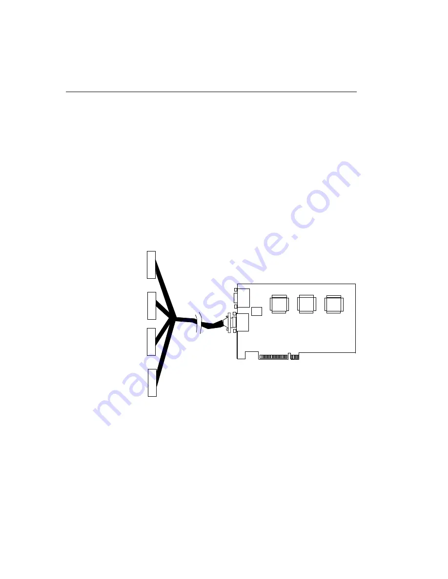
After making sure power to the computer is off, push the 15-pin
connector of one EP312 cable into the J1 socket at the rear of the
DT3130 Series, as shown in
, and tighten the screws on
the connector.
Figure 7: Connecting the EP312 Cable to Connector J1
J1
Trigger In 0+ 1
Trigger In 0
−
6
Trigger In 1+ 2
EP312
J2
+12 V 1
Trigger In 1
−
7
Strobe Out 0
+
5
Trigger In 2
+
3
Trigger In 2
−
8
Strobe Out 1
+
5
Strobe Out 1
−
4
Strobe Out 0
−
4
Strobe Out 2
+
5
Strobe Out 2
−
4
P3
+12 V Return 6
Strobe 0
Trigger
Strobe 1
Strobe 2
+12 V 4
+12 V Return 9
DT3130 Series
Board
Содержание DT3130 Series
Страница 1: ...DT3130 Series UM 17316 F Getting Started Manual...
Страница 8: ...About this Manual viii...
Страница 9: ...1 1 Overview Key Hardware Features 2 DT3130 Series Software 3 Getting Started Procedure 4...
Страница 44: ...Chapter 4 36...
Страница 45: ...37 5 Verifying Board Operation Overview 39 Installing DT Acquire 40 Using DT Acquire 41...


