background image

EMX-CDT User

’s Manual 

EMX-CDT User

’s Manual 3   

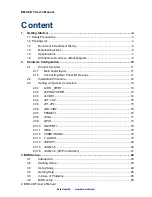
3.6.1


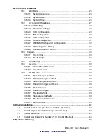
Main Menu ............................................................................................ 26


3.6.1.1


System Language ......................................................................... 26


3.6.1.2


System Date ................................................................................. 26


3.6.1.3


System Time ................................................................................. 26


3.6.2


Advanced BIOS settings ....................................................................... 27


3.6.2.1 ACPI Settings ................................................................................... 27


3.6.2.2    RTC Wake Settings ....................................................................... 28


3.6.2.3


CPU Configuration ........................................................................ 29


3.6.2.4


IDE Configuration .......................................................................... 30


3.6.2.5


USB Configuration ........................................................................ 30


3.6.2.6


Power Management ...................................................................... 31


3.6.2.7


W83627UHG Super IO Configuration ........................................... 32


3.6.2.8 


WatchDogTimer Setting ................................................................ 33


3.6.2.9


W83627UHG HW Monitor ............................................................. 34


3.6.3    Chipset ..................................................................................................... 34


3.6.3.1


Host bridge ................................................................................... 35


3.6.3.2


South bridge ................................................................................. 36


3.6.4


Boot settings ......................................................................................... 37


3.6.5


Security ................................................................................................. 38


3.6.5.1


Administrator Password ................................................................ 38


3.6.5.2


User Password.............................................................................. 38


3.6.6


Save & Exit ............................................................................................ 38


3.6.6.1


Save Changes and Exit ................................................................ 39


3.6.6.2


Discard Changes and Exit ............................................................ 39


3.6.6.3


Save Changes and Reset ............................................................. 39


3.6.6.4


Discard Changes and Reset ......................................................... 39


3.6.6.5


Save Changes .............................................................................. 39


3.6.6.6


Discard Changes .......................................................................... 39


3.6.6.7


Restore Defaults ........................................................................... 39


3.6.6.8


Save as user defaults ................................................................... 39


3.6.6.9


Restore as user defaults ............................................................... 40


3.6.6.10


Boot override ................................................................................ 40


4. Drivers Installation....................................................................................................... 41


4.1


Install Audio Driver (For Realtek ALC661 HD Audio) ................................... 42


4.2


Install Chipset Driver (For Intergated Cedar Trail) ........................................ 43


4.3


Install VGA Driver ......................................................................................... 44


4.4


Install LAN Driver (For Realtek 8111E Gigabit Ethernet) ............................. 45


5. Mechanical Drawing .................................................................................................... 46


Data Modul AG    -    www.data-modul.com 

Содержание EMX-CDT

Страница 1: ...User Manual 0 7 QWHO WRP HGDU 7UDLO 0LQL 7 0RWKHUERDUG LWK QWHO 3URFHVVRU 10 KLSVHW 1st Ed XQH 201 Version January 2013 ...

Страница 2: ...evices 11 2 2 Installation Procedure 12 2 3 Setting Jumpers Connectors 13 2 3 1 LVDS _PWR1 13 2 3 2 20PIN ATXPWR 13 2 3 3 JLVDS1 14 2 3 4 JU1 JU2 15 2 3 5 JP1 JP4 15 2 3 6 JIR1 JIR2 16 2 3 7 FPANEL1 16 2 3 8 JVGA 17 2 3 9 GPIO 17 2 3 10 JINVERT1 18 2 3 11 IRDA 18 2 3 12 FUSB1 FUSB2 19 2 3 13 F_AUDIO 19 2 3 14 JSPDIF1 20 2 3 15 JCOM1 6 20 2 3 16 JCOM1 6 9th Pin definition 21 3 BIOS Setup 22 3 1 Int...

Страница 3: ... 6 4 Boot settings 37 3 6 5 Security 38 3 6 5 1 Administrator Password 38 3 6 5 2 User Password 38 3 6 6 Save Exit 38 3 6 6 1 Save Changes and Exit 39 3 6 6 2 Discard Changes and Exit 39 3 6 6 3 Save Changes and Reset 39 3 6 6 4 Discard Changes and Reset 39 3 6 6 5 Save Changes 39 3 6 6 6 Discard Changes 39 3 6 6 7 Restore Defaults 39 3 6 6 8 Save as user defaults 39 3 6 6 9 Restore as user defaul...

Страница 4: ...ric charges As a safety precaution use a grounding wrist strap at all times Place all electronic components in a static dissipative surface or static shielded bag when they are not in the chassis Always note that improper disassembling action could cause damage to the motherboard We suggest not removing the heatsink without correct instructions in any circumstance If you really have to do this ple...

Страница 5: ...EMX CDT User s Manual EMX CDT User s Manual 5 1 3 Document Amendment History Revision Date By Comment 1st June 2012 Avalue Initial Release Data Modul AG www data modul com ...

Страница 6: ...empting to set up EMX CDT series or change the standard configurations Whilst all the necessary information is available in this manual we would recommend that unless you are confident you contact your supplier for guidance Please be aware that it is possible to create configurations within the CMOS RAM that make booting impossible If this should happen clear the CMOS settings see the description ...

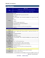
Страница 7: ...System CPU Onboard Intel Atom Processor D2550 Cedar Trail 1M Cache 1 86 GHz BIOS AMI 16MBit SPI BIOS System Chipset Intel NM10 I O Chip Winbond W83627UHG System Memory One 204 pin DDR3 1066 1333MHZ SO DIMM socket supports up to 4GB Max SSD NA Watchdog Timer Reset 1 to 255 sec min per step H W Status Monitor Monitoring temperature voltage and cooling fan status Auto throttling control when CPU over...

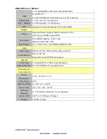
Страница 8: ...I Display 1920 x 1200 Internal LVDS 1440 x 900 Dual Display Yes LVDS VGA VGA HDMI HDMI LVDS Audio Audio Codec Realtek ALC661 HD Audio Decoding controller Audio Interface Mic in Line out Support On board S PDIF input output Ethernet LAN Chip 2 x Realtek RT8111E PCIe Gigabit Ethernet Ethernet Interface 10 100 1000 Base Tx Gigabit Ethernet Mechanical Environmental Power Requirement 12V 5V 5Vsb 3 3V P...

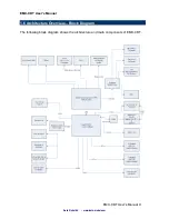
Страница 9: ...EMX CDT User s Manual EMX CDT User s Manual 9 1 6 Architecture Overview Block Diagram The following block diagram shows the architecture and main components of EMX CDT Data Modul AG www data modul com ...

Страница 10: ...EMX CDT User s Manual 10 EMX CDT User s Manual 2 Hardware Configuration Data Modul AG www data modul com ...

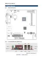
Страница 11: ...EMX CDT User s Manual EMX CDT User s Manual 11 2 1 Product Overview 2 1 1 Main board layout 2 1 2 Connecting Rear Panel I O Devices Data Modul AG www data modul com ...

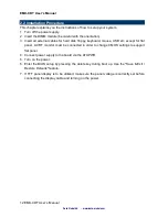
Страница 12: ...oard mouse USB etc except for flat panel A CRT monitor must be connected in order to change CMOS settings to support flat panel 4 Connect power supply to the board via the ATXPWR 5 Turn on the power 6 Enter the BIOS setup by pressing the delete key during boot up Use the Save Exit Restore Defaults feature 7 If TFT panel display is to be utilized make sure the panel voltage is correctly set before ...

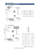
Страница 13: ... 5V 2 3 3 3V 1 2 Set JLVDS1 Pin1 2 5 6 VDDSAFE as 5V 2 3 Set JLVDS1 Pin1 2 5 6 VDDSAFE as 3 3V 2 3 2 20PIN ATXPWR Pin No Definition Pin No Definition 1 3 3V 2 3 3V 3 GND 4 5V 5 GND 6 5V 7 GND 8 PWR OK 9 5VSB 10 12V 11 3 3V 12 12V 13 GND 14 PS ON 15 GND 16 GND 17 GND 18 5V 19 5V 20 5V Data Modul AG www data modul com ...

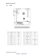
Страница 14: ...8 NC 9 LVDS0_P0 10 NC 11 GND 12 GND 13 LVDS0_N1 14 NC 15 LVDS0_P1 16 NC 17 GND 18 GND 19 LVDS0_N2 20 NC Pin No Definition Pin No Definition 21 LVDS0_P2 22 NC 23 GND 24 GND 25 LVDS0_CLKN 26 NC 27 LVDS0_CLKP 28 NC 29 GND 30 GND 31 LVDS_DDCPCLK 32 LVDS_DDCPDATA 33 GND 34 GND 35 LVDS0_N3 36 NC 37 LVDS0_P3 38 NC 39 NC 40 LVDS_VCON Data Modul AG www data modul com ...

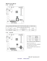
Страница 15: ...ini PCI e card in the Mini PCI e slot Enabled 2 3 MINIPCIE Disabled Enabled Enabled 2 3 5 JP1 JP4 Pin No Definition 1 2 MINIPCIE 2 3 M SATA 3 4 SATA2 When you want to use Wifi on MINIPCIE1 slot please set up JP1 JP4 as 1 2 When you want to use M SATA on MINIPCIE1 slot please set up JP1 JP4 as 2 3 When you use SATA2 connect please set up JP1 JP4 as 3 4 Data Modul AG www data modul com ...

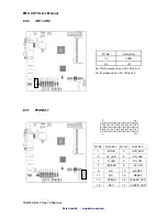
Страница 16: ... For COM2 please set up JIR1 JIR2 as 1 2 For IR please set up JIR1 JIR2 as 2 3 2 3 7 FPANEL1 Pin No Definition Pin No Definition 1 5VSB 2 HD_LED 3 P_LED 4 HD_LED 5 P_LED 6 PS_ON 7 SPEAK 8 PS_ON 9 NC 10 RESET 11 NC 12 RESET 13 SPEAK 14 SLEEP_LED 15 KEY 16 SLEEP_LED Data Modul AG www data modul com ...

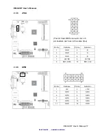
Страница 17: ...aders can t use in the same time Pin No Definition Pin No Definition 1 GND 2 R 3 GND 4 G 5 GND 6 B 7 HSYNC 8 VSYNC 9 DDC_DATA 10 DDC_CLK 2 3 9 GPIO Pin No Definition Pin No Definition 1 5V 2 12V 3 GPIO 4 GPIO 5 GPIO 6 GPIO 7 GPIO 8 GPIO 9 GPIO 10 GPIO 11 GND 12 GND Data Modul AG www data modul com ...

Страница 18: ...s Manual 2 3 10 JINVERT1 Pin No Definition Pin No Definition 1 12V 2 GND 3 BLEN 4 PWM 5 5V 2 3 11 IRDA Only for specially used Can t send data Pin No Definition Pin No Definition 1 VCC 2 3 IRRX 4 GND 5 IRTX Data Modul AG www data modul com ...

Страница 19: ...a 1 5 Data 0 6 Data 1 7 GND 8 GND 9 NC CUT 10 GND When JU1 JU2 jumpers are set to 2 3 FUSB2 USB7 will be disabled Please refer to P 15 2 3 4 for more information 2 3 13 F_AUDIO Pin No Definition 1 FRONT_MIC 2 GND 3 VREF_OUT 4 5V 5 FRONT_OUT_R 6 AUD_RET_R 7 GND 8 NC CUT 9 FRONT_OUT_L 10 AUD_RET_L Data Modul AG www data modul com ...

Страница 20: ... 20 EMX CDT User s Manual 2 3 14 JSPDIF1 Pin No Definition 1 NC 2 GND 3 OUT 2 3 15 JCOM1 6 Pin No Definition Pin No Definition 1 DCD 2 RXD 3 TXD 4 RTD 5 GND 6 DSR 7 RTS 8 CTS 9 RI 10 NC CUT Data Modul AG www data modul com ...

Страница 21: ...EMX CDT User s Manual 21 2 3 16 JCOM1 6 9th Pin definition COM1 to COM6 9th Pin definition Pin No Pin Definition JC11 12 13 CLOSE RI JC14 15 16 OPEN USE JC1 JC6 JC1 2 3 1 2 5V JC4 5 6 2 3 12V Data Modul AG www data modul com ...

Страница 22: ...EMX CDT User s Manual 22 EMX CDT User s Manual 3 BIOS Setup Data Modul AG www data modul com ...

Страница 23: ...ontrol over to the operating system While the BIOS is in control the Setup program can be activated in one of two ways By pressing Del immediately after switching the system on or By pressing the Del key when the following message appears briefly at the bottom of the screen during the POST Power On Self Test Press DEL to enter SETUP If the message disappears before you respond and you still wish t...

Страница 24: ... not save changes into CMOS Status Page Setup Menu and Option Page Setup Menu Exit current page and return to Main Menu key Increase the numeric value or make changes key Decrease the numeric value or make changes F1 key General help only for Status Page Setup Menu and Option Page Setup Menu F2 key Previous Values F9 key Reserved F10 key Save and Exit Navigating Through The Menu Bar Use the left a...

Страница 25: ...onger is able to boot the AMI BIOS supports an override to the CMOS settings which resets your system to its defaults The best advice is to only alter settings which you thoroughly understand To this end we strongly recommend that you avoid making any changes to the chipset defaults These defaults have been carefully chosen by both Award and your systems manufacturer to provide the absolute maximu...

Страница 26: ...configurations in your computer and set the system clock 3 6 1 1 System Language Use this option to select system language 3 6 1 2 System Date Use the system Date option to set the system date Manually enter the day month and year 3 6 1 3 System Time Use the system time option to set the system time Manually enter the hours minutes and seconds Note BIOS setup screens shown in this chapter are for ...

Страница 27: ...llowing sub menus Item Options Description Onboard Lan BootROM Control Disabled Default Enabled Enable or Disable Boot Option for Legacy Network Devices Launch Storage OpROM Disabled Enabled Default Enable or disable Boot Option for Legacy Mass storage devices With Option ROM 3 6 2 1 ACPI Settings You can use this item to set up ACPI Configuration Data Modul AG www data modul com ...

Страница 28: ...to RAM Default Select the highest ACPI sleep state the system will enter when the SUSPEND button is pressed Lock Legacy Resources Disabled Default Enabled Enables or Disables Lock of Legacy Resources 3 6 2 2 RTC Wake Settings Item Options Description Wake system with Fixed Time Disabled Default Enabled Enables or Disables wake on alarm event When enabled System will wake on the hr min sec specifie...

Страница 29: ...Linux OS optimized for Hyper Threading Technology and Disabled for other OS OS not optimized for Hyper Threading Technology Execute Disable Bit Disabled Enabled Default XD can prevent certain classed of malicious buffer overflow attacks when combined with a supporting OS Windows Server 2003 SP1 Windows XP SP2 SuSE Linux 9 2 RedHat Enterprise 3 Update 3 Limit CPUID Maximum Disabled Default Enabled ...

Страница 30: ...ller s Enabled Default Disabled SATA Ports 0 3 Device Names if Present and Enabled Configure SATA as IDE Default AHCI Select a configuration for SATA Controller 3 6 2 5 USB Configuration The USB configuration menu is used to read USB configuration information and configure USB Data Modul AG www data modul com ...

Страница 31: ... and Interrupt transfers Device reset time out 10sec 20sec Default 30sec 40sec USB mass storage device Start Unit command time out Device power up delay Auto Default Manual Maximum time the device will take before it properly reports itself to the Host Controller Auto uses default value for a Root port it is 100ms for a Hub port the delay is taken from Hub descriptor 3 6 2 6 Power Management Item ...

Страница 32: ...rial ports 3 6 2 7 1 Serial Port 1 2 3 4 5 6 Configuration Item Option Description Serial Port Enabled Default Disabled Enable or Disable Serial Port COM Change Settings Auto Default IO 3F8h IRQ 4 IO 3F8h IRQ 3 4 5 6 7 10 11 12 IO 2F8h IRQ 3 4 5 6 7 10 11 12 IO 3E8h IRQ 3 4 5 6 7 10 11 12 IO 2E8h IRQ 3 4 5 6 7 10 11 12 Select an optimal setting for Super IO device Data Modul AG www data modul com ...

Страница 33: ...78h IRQ 5 6 7 10 11 12 IO 278h IRQ 5 6 7 10 11 12 IO 3BCh IRQ 5 6 7 10 11 12 Select an optimal setting for Super IO device Device Mode STD Printer Mode Default SPP Mode EPP 1 9 and SPP Mode EPP 1 7 and SPP Mode ECP Mode ECP and EPP 1 9 Mode ECP and EPP 1 7 Mode Change the Printer Port mode 3 6 2 8 WatchDogTimer Setting Item Options Description WatchDogTimer Enabled Disabled Default WatchDogTimer S...

Страница 34: ...EMX CDT User s Manual 34 EMX CDT User s Manual 3 6 2 9 W83627UHG HW Monitor The H W Monitor shows the operating temperature fan speeds and system voltages 3 6 3 Chipset Data Modul AG www data modul com ...

Страница 35: ...ice which will be activated during POST This has no effect if external graphics present LCD Panel Type VBIOS Default Default 640x480 LVDS 800x600 LVDS 1024x768 LVDS 1280x1024 LVDS 1366x768 LVDS 1024x600 LVDS 1280x800 LVDS Select LCD panel used by Internal Graphics Device by selecting the appropriate setup item IGD Clock Source External Clock Default Internal Clock IGD clock selection Fixed Graphic...

Страница 36: ...troller Azalia Vci Enable Enabled Default Disabled Azalia supports 1 extended VC which when enabled overrides ICH VCp settings USB Function Enabled Default Disabled Control the USB UHCI USB 1 1 functions Disable from highest to lowest controller Onboard LAN 1 2 Controller Auto Default Enabled Disabled Enable Disable Onboard Lan Controller SMBus Controller Enabled Default Disabled Enable or Disable...

Страница 37: ...d Disabled Default Enables or Disables Quiet Boot Option GateA20 Active Upon Request Default Always UPON REQUEST GA20 can be disabled using BIOS services ALWAYS do not allow disabling GA20 this option is useful when any RT code is executed above 1MB Option ROM Messages Force BIOS Default Keep current Set display mode for Option ROM Interrupt 19 Capture Enabled Default Disabled Enabled Allows Optio...

Страница 38: ... setup program and is only asked for when entering the BIOS setup program By default no password is specified 3 6 5 2 User Password This setting specifies a password that must be entered to access the BIOS Setup Utility or to boot the system If only the User s password is set then this is a power on password and must be entered to boot or enter the BIOS setup program In the BIOS setup program the ...

Страница 39: ...IOS setup program are discarded The setup program then exits and reboots the controller 3 6 6 5 Save Changes Changes made to BIOS settings during this session are committed to NVRAM The setup program remains active allowing further changes 3 6 6 6 Discard Changes Any changes made to BIOS settings during this session of the BIOS setup program are discarded The BIOS setup continues to be active 3 6 ...

Страница 40: ...Boot override This option lists all possible bootable devices and allows the user to override the Boot Option Priorities list for the current boot If no changes have been made to the BIOS setup options the system will continue booting to the selected device without first rebooting If BIOS setup options have been changed and saved a reboot will be required and the boot override selection will not b...

Страница 41: ... EMX CDT User s Manual 41 4 Drivers Installation Note Installation procedures and screen shots in this section are for your reference and may not be exactly the same as shown on your screen Data Modul AG www data modul com ...

Страница 42: ... automatically If not locate Index htm and choose the product from the menu left or link to Driver_Audio Note The installation procedures and screen shots in this section are based on Windows 7 operation system If the warning message appears while the installation process click Continue to go on Step1 Click Next to Install Step 2 Select Finish to complete installation Data Modul AG www data modul ...

Страница 43: ... automatically If not locate the folder HTML and choose the product from the targeted folder Note The installation procedures and screen shots in this section are based on Windows 7 operating system Step 1 Locate Driver_Chipset Inf Step 4 Select Next to continue installation Step 2 Select Next to start setup Step 5 Select Finish to complete Installation Step 3 Select Yes to the next step Data Modu...

Страница 44: ...older HTML and choose the product from the targeted folder Note The installation procedures and screen shots in this section are based on Windows 7 operating system Step 1 Locate VGA Graphics Step 4 Select Next to continue installation Step 2 Select Next to start setup Step 5 Select Next to continue installation Step 3 Select Yes to the next step Step 6 Select Finish to complete installation Data ...

Страница 45: ...e of Avalue s products automatically If not locate Index htm and choose the product from the menu left or link to Driver_Network LAN Note The installation procedures and screen shots in this section are based on Windows 7 operation system Step 3 Click Finish to complete setup Step 1 Click Next to Install Step 2 Click Install to begin the installation Data Modul AG www data modul com ...

Страница 46: ...EMX CDT User s Manual 46 EMX CDT User s Manual 5 Mechanical Drawing Data Modul AG www data modul com ...

Страница 47: ...EMX CDT User s Manual EMX CDT User s Manual 47 Unit mm Data Modul AG www data modul com ...

Страница 48: ...EMX CDT User s Manual 48 EMX CDT User s Manual Unit mm Data Modul AG www data modul com ...

Страница 49: ...ce Scandinavia Lundsmindevej 5 DK 6000 Kolding Denmark Phone 45 75 224477 DATA MODUL France 7 rue Saint Christophe F 60300 BARON France Phone 33 3 44549699 DATA MODUL Italy S r l Regus Center Senigallia Via Senigallia 18 2 I 20161 Milano Italy Phone 39 02 64672509 DATA MODUL Iberia S L c Adolfo Pérez Esquivel 3 Edificio Las Americas III Oficina 40 28230 Parque Empresarial Las Rozas Madrid Spain Ph...

Отзывы: