Display User Manual
DDJ11752001
4-3-2007
Page 4
2
Hardware
2.1
Unpacking
Carefully remove the items from their package and store the packaging safely. After unpacking,
inspect the contents for any damage that may have occurred during shipment. In the event of
damage, refer to the '
Technical Support'
section of this manual.
2.2
Installation
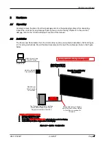
The Power and Serial cables from the Control Box must be connected at installation. Refer to Figure
2.1 for wiring instructions. Mount the Board securely and connect the cables as shown in the Figure
below.
Figure 2.1 – System Configuration
DATA IN /
POWER OUT
RS485 Serial
Cable from Box
to Cerel Box
Graphic Board Display
176 x 96 Pixels
Power Consumption for Display: 2400W
INSTALLATION INSTRUCTIONS
1.
Remove contents from Crate.
2.
Mount the Display securely.
3.
Connect the
DATA IN / POWER OUT
cable to the Box and to the Display.
4.
Connect 220V AC Mains Power cables to the Display.
Single Phase 220V AC
Mains Power to Display
RS232 to RS485
Transmitter Box
Control PC
RS232 Serial Cable
from PC to Box
The Displays’ Logic Board, Interface
Board, HWLDR Board and Power
Supply are located in Cerel Box.
Ribbon data cables to Display
and AC power out from Display
to Cerel Box are enclosed in
this cable.


