


45
45
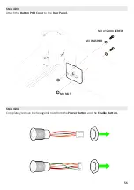
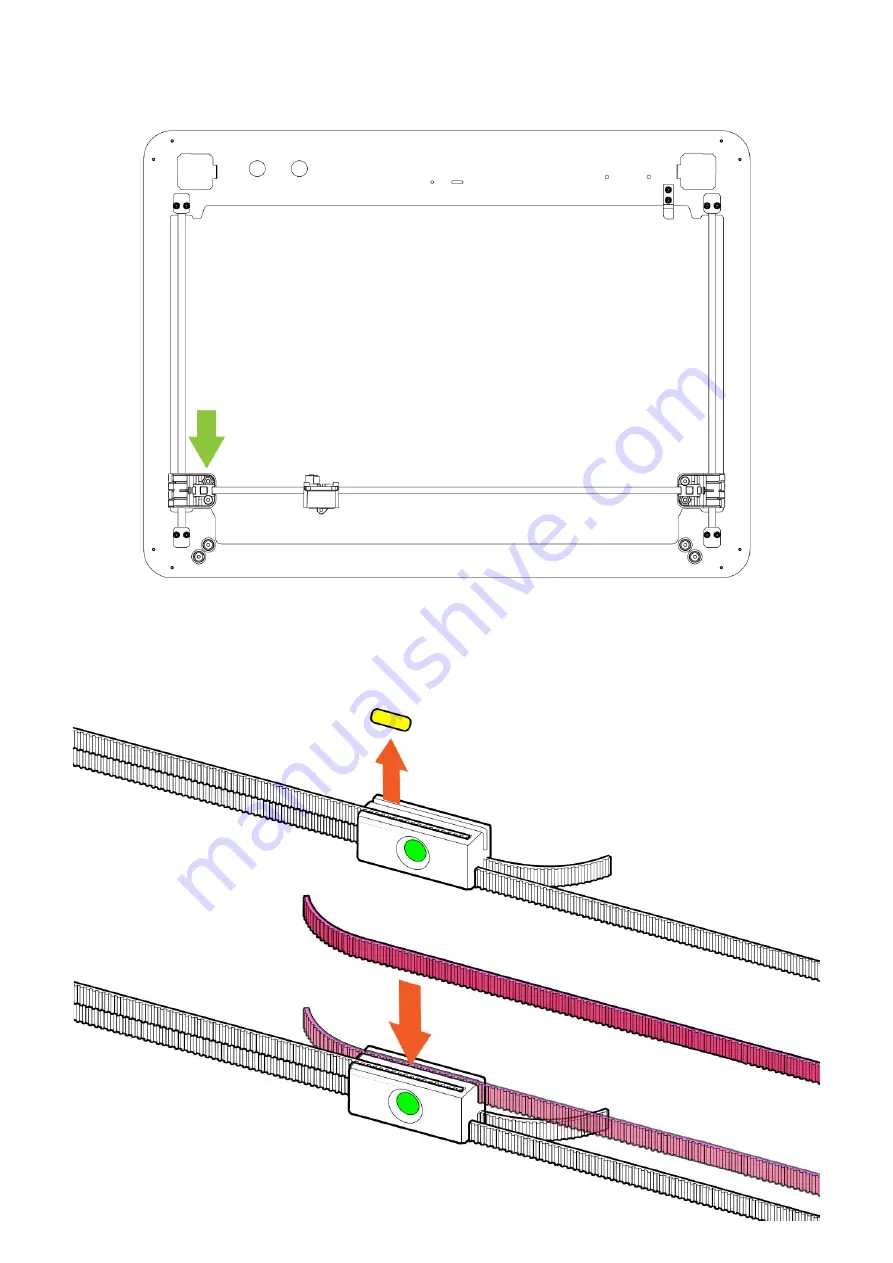
Remove the yellow belt tab and and press the
Belt into the Belt Hub as shown in the diagram.
Pull the belt tight. This should cause the left hand side
Gantry Carriage to get closer to the Top
Panel.
Apply just enough tension to the belt to remove the gap between the left hand side
Gantry
Carriage and the Top Panel.
Содержание Emblaser Core
Страница 1: ...Emblaser Core Assembly Manual Rev 1 32 User Assembly Manual English Darkly LabsR Kit Rev 1 0 ...
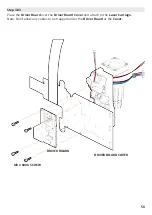
Страница 13: ...Step 1 04 Place the 4x Cable Management Clips in the recesses on the Rear Panel 13 ...
Страница 20: ...20 Step 2 05 Attach the Homing Trigger to the underside of the Top Panel M3 NUT M3 x 30mm SCREW M3 WASHER ...
Страница 21: ...21 Step 2 06 Assemble the four Idle Pulleys ...
Страница 33: ...33 33 Step 2 16 Route the Belt around the two Lower Position Idle Pulleys as shown ...
Страница 34: ...34 34 Step 2 17 Pass the Belt straight through the Gantry Carraige and around the Motor Pulley ...
Страница 35: ...35 35 Step 2 18 Route the Belt behind lower position pulley in the Gantry Carriage ...
Страница 41: ...41 41 Step 2 22 Route the Belt around the two Upper Position Idle Pulleys as shown ...
Страница 42: ...42 42 Step 2 23 Pass the Belt through the Gantry Carraige and around the Motor Pulley ...
Страница 43: ...43 43 Step 2 24 Route the Belt behind lower position pulley in the Gantry Carriage ...
Страница 52: ...Fold the Driver Board Cover as shown in the diagram Step 3 07 52 52 ...
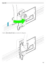
Страница 53: ...Clip In Latches Connect the FFC to the Driver Board connector socket indicated in the diagram below 53 53 ...
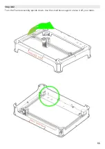
Страница 55: ...Turn the Frame Assembly upside down Use the small boxes again to raise it off your table Step 4 02 55 55 ...
Страница 68: ...Attach the Rubber Feet to the Base Plate as shown below Step 8 03 68 68 ...
Страница 76: ...Connect Workspace Camera cable to the Controller Board socket indicated Step 03 76 76 ...


