


Copyright © 2008 – 2019 DARE!! International
Page 34
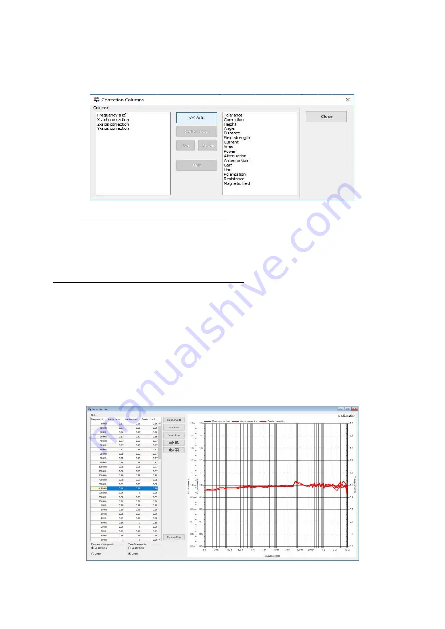
By individually selecting the X, Y and Z axis correction and pressing the ‘Add’ button, the requested
column type shall be added to the list of columns in the correction file. When you are done adding
the required columns, press ‘close’.
5.2.2
Add calibration data into the correction file
After adding the required column types the User correction data can be filled into the correction
file. This can be done manually, by entering the determined calibration values, or by using the
‘Copy/Paste’ function when calibration data is available as a Microsoft® Excel file.
WARNING:
Make sure that the correction file contains:
Exactly and only the columns:
"Frequency", "X-axis correction", "Y-axis correction" and "Z-axis correction"
At least 1 frequency row, and at most 200 frequency rows
The frequencies are listed in increasing order, and at least differ by 1 kHz
The frequency values are between 1000 Hz and 99999 MHz
Axis Correction values are between 0.01 and 3.00, with a maximum precision of 1/100.
(so, 1.234 is too precise)
After filling in this data into the correction file, this could for example look like the following (typical
RadiSense 10 frequency response calibration data).


