


EMB-OPT02 User’s Manual
4
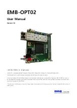
2. EMB-OPT02 Function
Each name and function description of EMB-OPT2 is as follows.
D
A
Q
s
ys
te
m
EMB-OPT02 Board
E
M
B
-
O
P
T
0
2
R
E
V
.
A
C
N
1
D7
JP1
w
w
w
.d
a
q
s
ys
te
m
.c
o
m
O
N
1
2
S
W
3
3
4
D10
U1
S
W
2
U3
J1
U
2
U
4
J
3
J2
D5
D6
D8
D9
[그림 2-1. EMB-OPT01 Layout]
[Table 1. EMB-OPT02 main function description]
No.
Name
Description
1
J1
Camera Link / DIO_IN0..47 Connector
2
U1, U3
1.2V, 1.8V, 3.3V Output
3
U2
FPGA
4
CN1
SFP(Small Form Factor Pluggable) Connector
5
U4
Serial Memory
6
JP1
12V Circular DC Jack
7
SW2
12V Power Switch
8
SW3
Connection mode selection switch
The LED shows the inner workings.
LED D5 : Detects Pclk (Pixel Clock) signal.
LED D6 : Detects Lval (Line Valid) signal.
LED D7 : Lights up when power is supplied to the board and initialization is completed.
LDE D8 : Detects Dval (Data Valid) signal.
LED D9 : Vsync (Vertical Sync.) /16 division signal
LED D10 Red is On when optical is connected.
LED D10 Green turns on when the optical channel (#0) horizontal sync signal (Hsync) is detected.


