


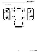


15
www.danvex.fi
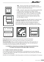
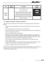
To set the parameters of the controller, 3 buttons are used: Setup (Set), Up (Up) and Down (Down).
The top panel displays the setting parameter, the bottom panel displays the parameter value.
Press the "Set" key (left) to set the parameters
.
Main settings
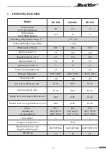
Step
Range
parameter
Description
Example
Images
1st press
buttons
"Setting"
("Set")
1 - 99 %
Setting the desired humidity value
Press the "Up" or "Down" button
to get the desired value.
How to set the following parameters similar.
2nd press
buttons
"Setting"
("Set")
1 - 10 %
Setting the response range at humidity
monitoring
Default value corresponds to
"05"(5%).
For example: set
Sd=50%, SHC=05%.
The dehumidifier will work until the humidity
is reaches 45%, then turns off.
When the relative humidity level in the drying
zone reaches 50%, the dehumidifier will restart.
3rd press
buttons
"Setting"
("Set")
-20 - +20 %
Humidity Sensor Calibration
If you have a third party current humidity meter
that you trust and in the same area/ conditions
it shows a different value from the value
on the controller display, do calibration
according to your instrument.
4th press
buttons
"Setting"
("Set")
1
Device address ID (not used).
No change is required.
5th press
buttons
"Setting"
("Set")
1/0
Universal parameter for dryer or humidifier,
sets the type of operation when reaching
the value of parameter
Sd.
CCо = 1 -
for dehumidification mode(controller
turns off the device when it reaches
the specified humidity parameter
);
CCо = 0 -
for humidification mode (controller
starts the device when it reaches set parameter
).


