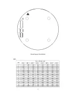
background image

18 


13 

ON 

OFF 

ON 

ON 

OFF 

OFF 

OFF 

OFF 

14 

OFF 

ON 

ON 

ON 

OFF 

OFF 

OFF 

OFF 

15 

ON 

ON 

ON 

ON 

OFF 

OFF 

OFF 

OFF 

16 

OFF 

OFF 

OFF 

OFF 

ON 

OFF 

OFF 

OFF 

17 

ON 

OFF 

OFF 

OFF 

ON 

OFF 

OFF 

OFF 

18 

OFF 

ON 

OFF 

OFF 

ON 

OFF 

OFF 

OFF 

… 

… 

255 

ON 

ON 

ON 

ON 

ON 

ON 

ON 

ON 


Using J1 former eight dips to set up the camera’s address, ranges from 0

255. 

DIP-1 to DIP-8 means a eight binary

DIP-8 means the highest bit, DIP-1 means 

the lowest bit. 

Some address shown as below: 


2.

Baud  Rate  Setting

Using  J1  DIP  9  and  DIP10  to  set  up  the  baud  rate, 

2400bps.4800bps.9600bps.19200bps optional. 

Pelco D uses 2400 Baud Rate


Baud Rate 

State of J1 


DIP-9 

DIP-10 

    2400 

OFF 

OFF 

4800 

ON 

OFF 

9600 

OFF 

ON 

19200 

ON 

ON 


3.

Protocol Setting

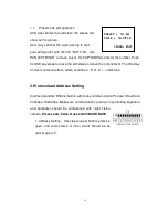
Support PELCO-D and PELCO-P protocols. J5 DIP1 used to 

choose  the  camera’s  communication  protocol,  DIP1  “ON”  means  PELCO-P

DIP1 “OFF” means PELCO-D.
 

Содержание DLS1798LA3P9S

Страница 1: ...DLS1798LP Thermal PTZ Camera Installation and Operations Manual Model Number DLS1798LA3P9S NTSC DLS1798LB3P9S PAL Description Thermal and 36x CCD PTZ Camera ...

Страница 2: ...s product Please read this operation manual carefully before using it as it may provide User with correct technical information on how to properly do the installation Please contact us if User comes across problems that are not mentioned in this instruction We will supply User with additional technical support ...

Страница 3: ...se contact factory and remember not to try and repair it without instructions from Dante 6 In order to protect the device and people this device need to be installed on firm flat area 7 Please install appropriate surge protection equipment to avoid damage from power surge or lightning 8 Use this device within the limitation of humidity and temperature 9 To protect the imaging components from damag...

Страница 4: ...allation step 4 4 System connection reference 7 Part Three Operation Introduction 8 1 Function Introduction 8 2 Menu Setup Instruction 9 3 Protocol and Address Setting 16 Part Four Quality guarantee and after sales service 19 1 Quality Guarantee and After sales Service 19 Appendix I Common Problems Analysis 19 Appendix II RS 485 LINE 20 Appendix III Cable Spec List all countries 22 ...

Страница 5: ...and has a clear image not restricted by light low light color to black and white camera for continuous monitoring day and night integrated pan tilt for multiple movement directions no blind spot monitoring and high accurate orientation high intelligent easy to operate and maintain smart shell with professional design light firm thermo stabilization anti corrosion waterproof and acid rain proof low...

Страница 6: ...00K Focal length 50mm FOV 13 9 11 1 Spatial resolution 0 76mrad Lens control Electronic focus Image process 2X electronic zoom palette colors Pan tilt Pan speed 0 50 s Tilt speed 0 50 s Presets 128 at most Cruise function 6 cruise paths 20 presets for each path Self checking 40s Interface Power supply interface Terminal Block Other interface RS422 2 BNC video output 2 alarm input 1 alarm output En...

Страница 7: ...ust be considered integrated with the building lighting proof requirements and must comply with the national standards and industry standards The ground system must meet the both radio frequency and electrical safety requirements and must not short connect or mixed connect to the electrical network zero curve When the system connect GND separately the grounding resistance must be less than 4Ω grou...

Страница 8: ...dip switch according to the address set up instruction to set up the address connect the camera to the resistor c Re install the bottom plate please maintain the unit airproof and waterproof d Using four pieces M3X8 screw to fix the shield to camera then using four pieces M8X25 screw and four pieces M8 nut to fix the whole device to the bracket ...

Страница 9: ...tion please connect the aviation plug pinout according to the definition below then connect to the device Definition as follows Power supply control signal input video signal output all connect with one cable with 12 PINS See below ...

Страница 10: ...nd cable with 7 core aviation connector see below 7 core aviation pin connector definition PIN NO Definition Remark 1 ALARM_OUT gray Alarm output 2 ALARM_OUT yellow Alarm output 4 ALARM_IN1 blue Alarm input 1 5 ALARM_IN2 white Alarm input 2 6 ALARM_COM black Alarm input ground Note 1 Please go ahead with the bolts M6 45 and M6 nuts which are equipped with the camera If need to change bolts because...

Страница 11: ...7 4 System connection reference Thermal camera should be connected with other equipment to form a system The following is the simple sketch ...

Страница 12: ... a state of color Also when the light outside is lower than set the camera will automatically change into a state of black white c Zoom rate adjust User may move the lens NEAR or FAR to adjust image d Focal length automatic adjusts camera uses image identity technology to achieve automatic focus e Back light compensation when the background is dark or unclear User may open the back light compensat...

Страница 13: ...hs in 40 seconds and imitate it may finish the action according to User s operation and data saves when power off e Character adding function Screen may show camera s address and number of presets f Short Long focal length shift function The night vision camera may adjust its pan tilt shifting speed automatically according to the focal length The larger magnification the slower shifting speed to m...

Страница 14: ... Enter the submenu of camera parameter set 2 1 3 CONTROL SETUP Enter the submenu of thermal camera control parameter set 2 1 4 THERM IMAGE SET Enter the submenu of thermal image which may be displayed on both videos 2 1 5 PROGRAM Enter the submenu of thermal camera enhancement function 2 1 6 THERM DEFAULT SET recover thermal camera default parameter 2 1 7 CAM DEFAULT SET Recover the camera s defau...

Страница 15: ...lay will be open 2 2 6 CROSS DIS choose the cross display method total four options they are ALL Double Video Display CAM Visible Video Display THERM Thermal Video Display NONE None Video Display 2 2 7 GRID DIS choose the grid display method total four options they are ALL Double Video Display CAM Visible Video Display THERM Thermal Video Display NONE None Video Display 2 2 8 ANGLE DIS It appears ...

Страница 16: ...nu of set automatic return function 2 4 2 1 AUTO HOME When this item is ON open the automatic return function It means that if the user has no action within a period of time the camera will return to HOME When the camera is in a state of patrolling it will not return to HOME When the camera doesn t need to return to HOME please set this item in OFF 2 4 2 2 HOME POS HOME is the return point For exa...

Страница 17: ...n the system will work this function for two minutes and then closed 2 4 7 RETURN Return to the main menu 2 5 THERM IMAGE SET when call this item thermal camera s menu will be shown on thermal video CCD camera will be temporarily exit from menu Thermal camera s menu show as image 2 5 1 BRIGHT Set brightness default is auto 2 5 2 CONTRA Set contrast default is auto 2 5 3 GAMMA Set Gamma default is ...

Страница 18: ...Push CLOSE key to save the current position and return 2 6 3 RUN AUTO PAN Press OPEN to start scan function and exit the menu Before running please first set up the start point and end point of scan which may be separately set by the first and second item of the menu 2 6 4 SET TITLE Set the title of pre setting point Only the former 63 pre setting points may have title Use PAN LEFT PAN RIGHT to ch...

Страница 19: ...rs the edit state the screen will display as follows NO tracking point number POS preset points number TM the staying time at this pre setting point SEQ 01 displays the current setup is 1 CLOSE EXIT push CLOSE to exit The top line and bottom line show the indicating information the middle shows every tracking paths information Every line shows 2 tracking points parameter Use PAN LEFT RIGHT to move...

Страница 20: ...endment The title may at most contain 8 letters which could be 0 9 A Z and blank 3 Protocol and Address Setting Interface standard RS422 built in with many communication Protocol Baud rate 2400bps 19200bps Make sure communication protocol in controlling keyboard and computer should be compliance with night vision camera Please note Pelco D uses 2400 BAUD RATE 1 Address Setting this step request bo...

Страница 21: ...FF OFF OFF OFF OFF OFF 3 ON ON OFF OFF OFF OFF OFF OFF 4 OFF OFF ON OFF OFF OFF OFF OFF 5 ON OFF ON OFF OFF OFF OFF OFF 6 OFF ON ON OFF OFF OFF OFF OFF 7 ON ON ON ON ON OFF OFF OFF 8 OFF OFF OFF ON OFF OFF OFF OFF 9 ON OFF OFF ON OFF OFF OFF OFF 10 OFF ON OFF ON OFF OFF OFF OFF 11 ON ON OFF ON OFF OFF OFF OFF 12 OFF OFF ON ON OFF OFF OFF OFF Add ...

Страница 22: ... DIP 1 to DIP 8 means a eight binary DIP 8 means the highest bit DIP 1 means the lowest bit Some address shown as below 2 Baud Rate Setting Using J1 DIP 9 and DIP10 to set up the baud rate 2400bps 4800bps 9600bps 19200bps optional Pelco D uses 2400 Baud Rate Baud Rate State of J1 DIP 9 DIP 10 2400 OFF OFF 4800 ON OFF 9600 OFF ON 19200 ON ON 3 Protocol Setting Support PELCO D and PELCO P protocols ...

Страница 23: ...but has no image Wrong connection of video cable change Not good connection of video cable eliminate Video camera is damaged change after self inspect but may not control Wrong connection of control signal correct Wrong match of address Reset the controller s address Wrong match of protocol Adjust the controller s protocols to match thermal camera Not steady image Not good connection of video line...

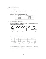
Страница 24: ...rthest Transmission Distance 2400 Bps 1800m 4800 Bps 1200m 9600 Bps 800m 3 Connection and terminal resistance RS485 industry line requires chain connection among all devices and both ends should be with 120Ωterminal resistance 120Ω 120Ω 1 2 3 4 32 But D section should not exceed 7 m Connection of 120Ω resistance this resistance has been ready on circuit board and default is that it s on 2 3 and 12...

Страница 25: ...ct farthest two devices As following sketch 1 and 15 are not compatible with RS485 it result to signal reflection and anti jamming ability reduction Regarding this problem we recommend to use RS485 Divider which may change Star Chain to suitable connection way and avoid problems to promote communication ...

Страница 26: ...100 38 42 0 00785 0 110 37 41 0 00950 0 130 36 39 0 01327 0 140 35 0 01539 0 160 34 37 0 02011 0 180 33 0 02545 0 200 32 35 0 03142 0 230 31 0 04115 0 250 30 33 0 04909 0 290 29 31 0 06605 0 330 28 30 0 08553 0 350 27 29 0 09621 0 400 26 28 0 1237 0 450 25 0 1602 0 560 24 24 0 2463 0 600 23 23 0 2827 0 710 22 22 0 3958 0 750 21 0 4417 0 800 20 21 0 5027 0 900 19 20 0 6362 1 000 18 19 0 7854 1 250 ...

Отзывы: