


Enhanced FM Synthesizer Instruction Manual
IM10-OS3AH
29 - 71.4 MHz - Synthesizer Alignment
14
If a TP4 reading of approxi2.3VDC
is unattainable through adjustment of C24,
then the coarse frequency jumpers, JU2-JU4
require modifi cation in order to pull the VCO
tune range within the adjustment range of fi ne
tuning capacitor C24. The top synthesizer
cover must be removed in order to gain
access to the coarse frequency jumpers.
The coarse frequency jumpers (JU2-JU4)
may be considered to be a selectable binary
weighted capacitor element with JU2 being the
most signifi cant “bit” and JU4 being the least
signifi cant “bit”. The tuning resolution size is
approximately 12pF (JU4). If the tuning voltage
remains higher than +2.3VDC, decrease the
tuning jumper setting by 1 “bit” position and re-
adjust C24 in an attempt to a2.3VDC at
TP4. For example, if coarse frequency jumpers
JU2-JU4 are all installed and represented by
111 then a decrease by 1 “bit” position (12pF)
is represented by a binary jumper selection of
110; jumper JU4 is not installed and jumpers
JU2, JU3 are installed. Continue to decrease
the jumper position one “bit” at a time until the
synthesizer regains lock with TP4 adjusted
(C24) for +2.3VDC. If the tuning voltage remains
lower than +2.3VDC, increase the jumper
setting by 1 “bit” position and re-adjust C24 in an
attempt to a2.3VDC at TP4. Repeat this
procedure until +2.3VDC is achieved at TP4.
It is important to check the loop control voltage
at TP4 when multiple synthesizer channels have
been programmed. All channel selections should
result in a TP4 voltage within a +1.0 to +4.0VDC
range. Adjust the fi ne-tuning capacitor C24 to
center multiple channel voltages symmetrically
about +2.3VDC. Channel selections beyond
the tuning range capability of the synthesizer
will result in unlocked operation. The tuning
range capability of this synthesizer model is
listed in the Therory of Operation section.
Reference Frequency Alignment
To adjust the output frequency of the synthesizer
the reference frequency of the TCXO is
adjusted. Note this adjustment is only valid when
the internal reference is selected (JU1 in the
B position on the analog board). To adjust the
internal TCXO referency frequency adjust the
synthesizer TCXO fi ne frequency potentiometer
RV1 until the correct output frequency is
achieved. Access to this potentiometer is
through an opening in the synthesizer top cover.
An RF power level of approxi5dBm
±2dBm should be measured at the synthesizer’s
SMB output connector J2. The frequency should
be within ±1 ppm of the desired operating
frequency. Reference frequency adjustments
should be made at room temperature (+25°C)
after a ten minute stabilization period.
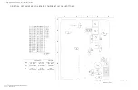
JUMPER CONFIGURATION
The synthesizer’s surface mount solder
jumpers are clearly marked on both of it’s
digital and analog circuit boards. Refer
to the ‘Digital Board Component Layout
(Bottom)’ diagram in this section and the
‘Analog Board Component Layout (Top)’
diagram for jumper locations. The following
list details the required jumper confi guration
for the two synthesizer operating modes:
1) Internal reference. Install jumper JU1 in the B
position, on the Analog Board (Standard). The
internal temperature compensated crystal
oscillator (TCXO) provides the reference
signal with a stability of ±1 ppm from -30°C
(Optional -40°C) to +60°C.
2) External reference input. Install jumper JU1
in the A position on the Analog Board. This
mode is used in applications requiring better
than ±1 ppm frequency stability. An external
reference signal must be provided at the
synthesizer’s SMB connector J1. An optional
front panel external reference connector is
available as an option for transmitters and
receivers.
3) Reference Frequency Select. Install jumper
JU2 on the Digital Board to select a 10.0MHz
reference frequency. When not installed, the
reference frequency is by default 9.6MHz.
JU2 is used by the microcontroller to establish
the correct reference frequency division ratio.
(the Synthesizer module must be removed to
change jumper JU2 on the digital board.)
Note: Care must be exercised when reinstalling
the synthesizer module on the Transmitter
Main board or the IF/Audio board. Pay careful
attention to pin alignment before pressing the
synthesizer module into its mating sockets..
Содержание OSR-3H061
Страница 4: ...Enhanced FM Synthesizer Instruction Manual IM10 OS3AH iv This Page Intentionally Left Blank...
Страница 6: ...Enhanced FM Synthesizer Instruction Manual IM10 OS3AH 2 This Page Intentionally Left Blank...
Страница 8: ...Enhanced FM Synthesizer Instruction Manual IM10 OS3AH 4 This Page Intentionally Left Blank...
Страница 26: ...Enhanced FM Synthesizer Instruction Manual IM10 OS3AH 22 This Page Intentionally Left Blank...
Страница 36: ...Enhanced FM Synthesizer Instruction Manual IM10 OS3AH 32 This Page Intentionally Left Blank...
Страница 54: ...Enhanced FM Synthesizer Instruction Manual IM10 OS3AH 50 This Page Intentionally Left Blank...
Страница 64: ...Enhanced FM Synthesizer Instruction Manual IM10 OS3AH 60 This Page Intentionally Left Blank...
Страница 82: ...Enhanced FM Synthesizer Instruction Manual IM10 OS3AH 78 This Page Intentionally Left Blank...
Страница 94: ...Enhanced FM Synthesizer Instruction Manual IM10 OS3AH 90 This Page Intentionally Left Blank...