


4.4.2 Status Word according to PROFIdrive
Profile (STW)
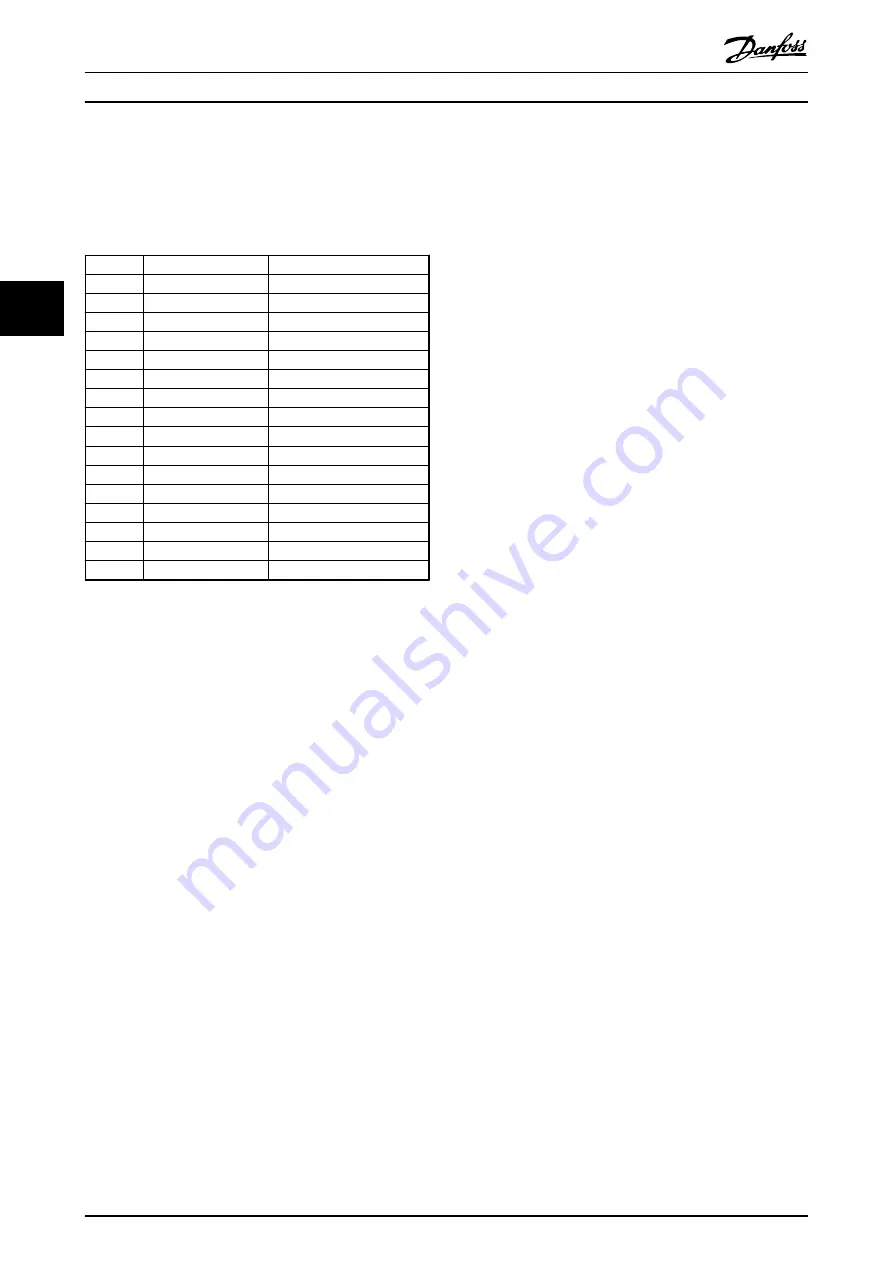
The status word is used to notify a master (e.g. a PC)
about the status of a follower.
Bit
Bit=0
Bit=1
00
Control not ready
Control ready
01
Drive not ready
Drive ready
02
Coasting
Enable
03
No error
Trip
04
OFF 2
ON 2
05
OFF 3
ON 3
06
Start possible
Start not possible
07
No warning
Warning
08
Speed
≠
reference
Speed = reference
09
Local operation
Bus control
10
Out of frequency limit Frequency limit ok
11
No operation
In operation
12
Drive OK
Stopped, autostart
13
Voltage OK
Voltage exceeded
14
Torque OK
Torque exceeded
15
Timer OK
Timer exceeded
Table 4.7 Status Word Bits
Explanation of the status bits
Bit 00, Control not ready/Ready
When bit 00="0", bit 00, 01 or 02 of the control word is "0"
(OFF 1, OFF 2 or OFF 3) - or the frequency converter is
switched off (trip).
When bit 00="1", the frequency converter control is ready,
but there is not necessarily power supply to the unit
present (in the event of external 24 V supply of the control
system).
Bit 01, VLT not ready/Ready
Same significance as bit 00, however, there is a supply of
the power unit. The frequency converter is ready when it
receives the necessary start signals.
Bit 02, Coasting/Enable
When bit 02="0", bit 00, 01 or 02 of the control word is "0"
(OFF 1, OFF 2 or OFF 3 or coasting) - or the frequency
converter is switched off (trip).
When bit 02="1", bit 00, 01 or 02 of the control word is
"1"; the frequency converter has not tripped.
Bit 03, No error/Trip
When bit 03="0", no error condition of the frequency
converter exists.
When bit 03="1", the frequency converter has tripped and
requires a reset signal before it can start.
Bit 04, ON 2/OFF 2
When bit 01 of the control word is "0", bit 04="0".
When bit 01 of the control word is "1", bit 04="1".
Bit 05, ON 3/OFF 3
When bit 02 of the control word is "0", bit 05="0".
When bit 02 of the control word is "1", bit 05="1".
Bit 06, Start possible/Start not possible
If PROFIdrive has been selected in
, bit 06 is "1" after a switch-off acknowl-
edgment, after activation of OFF2 or OFF3, and after
switching on the mains voltage.
Start not possible
is reset,
with bit 00 of the control word being set to "0" and bit 01,
02 and 10 being set to "1".
Bit 07, No warning/Warning
Bit 07=“0” means that there are no warnings.
Bit 07=“1” means that a warning has occurred.
Bit 08, Speed≠reference/Speed=reference
When bit 08="0", the current speed of the motor deviates
from the set speed reference value. This may occur, for
example, when the speed is being changed during start/
stop through ramp up/down.
When bit 08="1", the current speed of the motor
corresponds to the set speed reference value.
Bit 09, Local operation/Bus control
Bit 09="0" indicates that the frequency converter has been
stopped with [Stop] on the LCP, or that [Linked to hand]
or [Local] has been selected in
3-13 Reference Site
.
When bit 09="1", the frequency converter can be
controlled through the serial interface.
Bit 10, Out of frequency limit/Frequency limit OK
When bit 10="0", the output frequency is outside the limits
set in
4-52 Warning Speed Low
and
4-53 Warning Speed
High
.
When bit 10="1", the output frequency is within the
indicated limits.
Bit 11, No operation/Operation
When bit 11="0", the motor does not turn.
When bit 11="1", the frequency converter has a start
signal, or the output frequency is higher than 0 Hz.
Bit 12, Drive OK/Stopped, autostart
When bit 12="0", there is no temporary overloading of the
inverter.
When bit 12="1", the frequency converter has stopped due
to overloading. However, the frequency converter has not
switched off (trip) and starts again after the overloading
has ended.
Bit 13, Voltage OK/Voltage exceeded
When bit 13="0", the voltage limits of the frequency
converter are not exceeded.
When bit 13="1", the direct voltage in the intermediate
circuit of the frequency converter is too low or too high.
Bit 14, Torque OK/Torque exceeded
When bit 14="0", the motor torque is below the limit
selected in
4-16 Torque Limit Motor Mode
and
4-17 Torque
Limit Generator Mode
.
When bit 14="1", the limit selected in
4-16 Torque Limit
Motor Mode
or
4-17 Torque Limit Generator Mode
is
exceeded.
Control
Programming Guide
18
Danfoss A/S © Rev. 05/2014 All rights reserved.
MG37G102
4
4
Содержание VLT PROFIBUS DP MCA 101
Страница 2: ......
Страница 59: ...Index Programming Guide MG37G102 Danfoss A S Rev 05 2014 All rights reserved 57...


