•
•
•
•
-
N O T I C E
The PSM 510, DAM 510, and optional ACM 510 and EXM 510 must be mounted in a control cabinet.
5.3 Grounding for Electrical Safety
5.3.1 Grounding the ISD 511 Servo Drive
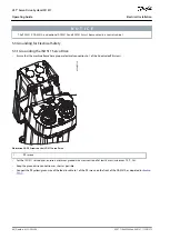
Ensure that the machine frame has a proper electrical connection to 1 of the 2 dedicated PE screws.
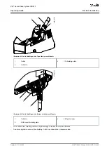
1
e30bj997.10
Illustration 20: PE Screws on the ISD 511 Servo Drive
1
PE screws
For the ISD 511 servo drives, ensure a minimum ground wire cross-section of at least 4 mm
2
(minimum 70 °C, Cu).
Keep the ground wire connections as short as possible.
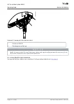
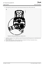
Connect the PE yellow/green wire of the feed-in cable to 1 of the PE screws on the front of the DAM 510, as depicted in
AQ377148425069en-000101
/ 130R1213
46 | Danfoss A/S © 2023.08
Electrical Installation
VLT® Servo Drive System ISD 511
Operating Guide
Содержание VLT ISD 511
Страница 1: ...Operating Guide VLT Servo Drive System ISD 511 drives danfoss com...
Страница 2: ......


