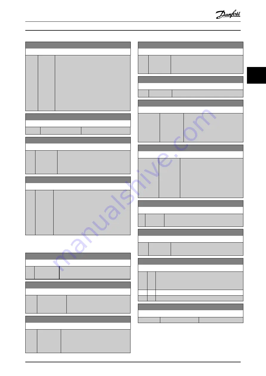
16-16 Torque [Nm]
Range:
Function:
0 Nm
*
[-3000 -
3000
Nm]
View the torque value with sign, applied to
the motor shaft. Linearity is not exact between
110% motor current and torque in relation to
the rated torque. Some motors supply more
than 160% torque. Consequently, the min.
value and the max. value will depend on the
max. motor current as well as the motor used.
The value is filtered, and thus approx. 1.3 s
may pass from when an input changes value
to when the data read-out values change.
16-17 Speed [RPM]
Range:
Function:
0 RPM
*
[-30000 - 30000 RPM]
View the actual motor RPM.
16-18 Motor Thermal
Range:
Function:
0 %
*
[0 - 100 %] View the calculated thermal load on the
motor. The cut-out limit is 100%. The basis
for calculation is the ETR function selected in
16-22 Torque [%]
Range:
Function:
0 %
*
[-200 -
200 %]
This is a read out parameter only.
Shows the actual torque yielded in percentage
of the rated torque, based on the setting of the
motor size and rated speed in
or
and
This is the value monitored by the
Broken Belt
Function
set in parameter group 22-6*.
3.13.2 16-3* Drive Status
16-30 DC Link Voltage
Range:
Function:
0 V
*
[0 - 10000 V] View a measured value. The value is filtered
with an 30 ms time constant.
16-32 Brake Energy /s
Range:
Function:
0 kW
*
[0 - 675000 kW] View the brake power transmitted to
an external brake resistor, stated as an
instantaneous value.
16-33 Brake Energy /2 min
Range:
Function:
0 kW
*
[0 - 500 kW] View the brake power transmitted to an
external brake resistor. The mean power is
calculated on an average basis for the
most recent 120 s.
16-34 Heatsink Temp.
Range:
Function:
0 °C
*
[0 - 255 °C] View the frequency converter heatsink
temperature. The cut-out limit is 90
±
5
°
C,
and the motor cuts back in at 60
±
5
°
C.
16-35 Inverter Thermal
Range:
Function:
0 %
*
[0 - 100 %] View the percentage load on the inverter.
16-36 Inv. Nom. Current
Range:
Function:
Size related
*
[0.01 -
10000 A]
View the inverter nominal current,
which should match the nameplate
data on the connected motor. The
data are used for calculation of
torque, motor protection, etc.
16-37 Inv. Max. Current
Range:
Function:
Size
related
*
[0.01 -
10000 A]
The current that FC 103 can deliver
during 1 min./10 min. This value
changes depending on whether it is a
high overload or normal overload
application. The data are used for
calculation of torque, motor
protection, etc.
16-38 SL Controller State
Range:
Function:
0
*
[0 - 100 ] View the state of the event under execution by
the SL controller.
16-39 Control Card Temp.
Range:
Function:
0 °C
*
[0 - 100 °C] View the temperature on the control card,
stated in
°
C
16-40 Logging Buffer Full
Option: Function:
View whether the logging buffer is full (see parameter
group 15-1*). The logging buffer will never be full
when
is set to
[0] Log always
.
[0]
*
No
[1]
Yes
16-41 LCP Bottom Statusline
Range:
Function:
0
*
[0 - 0 ]
Parameter Description
VLT
®
Refrigeration Drive Programming Guide
MG16H102 - VLT
®
is a registered Danfoss trademark
105
3
3


