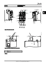
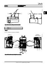

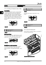

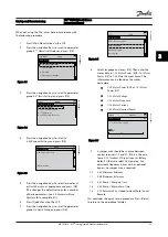


2.5 Control Wiring Connection
•
Isolate control wiring from high power
components in the adjustable frequency drive
•
If the adjustable frequency drive is connected to
a thermistor, for PELV isolation, optional
thermistor control wiring must be reinforced/
double insulated. A 24 V DC supply voltage is
recommended.
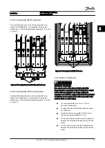
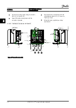
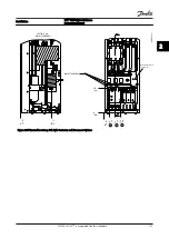
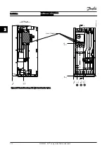
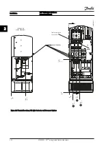
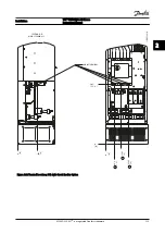
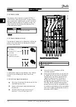
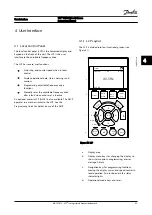
2.5.1 Access
All terminals to the control cables are located underneath
the LCP on the inside of the adjustable frequency drive. To
access, open the door (IP21/54) or remove the front panel
(IP20).
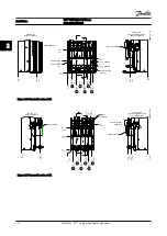
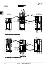
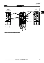
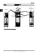
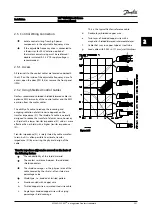
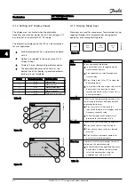
2.5.2 Using Shielded Control Cables
Danfoss recommends braided shielded/armored cables to
optimize EMC immunity of the control cables and the EMC
emission from the motor cables.
The ability of a cable to reduce the incoming and
outgoing radiation of electric noise depends on the
transfer impedance (Z
T
). The shield of a cable is normally
designed to reduce the transfer of electric noise; however,
a shield with a lower transfer impedance (Z
T
) value is more
effective than a shield with a higher transfer impedance
(Z
T
).
Transfer impedance (Z
T
) is rarely stated by cable manufac-
turers, but it is often possible to estimate transfer
impedance (Z
T
) by assessing the physical design of the
cable.
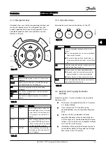
Transfer impedance (Z
T
) can be assessed on the basis of
the following factors:
•
The conductibility of the shield material
•
The contact resistance between the individual
shield conductors
•
The shield coverage, i.e., the physical area of the
cable covered by the shield - often stated as a
percentage value
•
Shield type, i.e., braided or twisted pattern
a.
Aluminum-clad with copper wire
b.
Twisted copper wire or armored steel wire cable
c.
Single-layer braided copper wire with varying
percentage shield coverage.
This is the typical Danfoss reference cable.
d.
Double-layer braided copper wire
e.
Twin layer of braided copper wire with a
magnetic, shielded/armored intermediate layer
f.
Cable that runs in copper tube or steel tube
g.
Lead cable with 0.043 in [1.1 mm] wall thickness
Figure 2.24
Installation
VLT
®
HVAC Drive D-Frame
Instruction Manual
MG16D222 - VLT
®
is a registered Danfoss trademark
2-21
2
2
Содержание VLT FC 100
Страница 1: ...MAKING MODERN LIVING POSSIBLE Instruction Manual 110 400 kW D Frame VLT HVAC Drive FC 100...
Страница 2: ......
Страница 4: ...Safety VLT HVAC Drive D Frame Instruction Manual MG16D222 VLT is a registered Danfoss trademark...
Страница 8: ...Contents VLT HVAC Drive D Frame Instruction Manual MG16D222 VLT is a registered Danfoss trademark...
Страница 14: ...Introduction VLT HVAC Drive D Frame Instruction Manual 1 6 MG16D222 VLT is a registered Danfoss trademark 1 1...
Страница 40: ...Installation VLT HVAC Drive D Frame Instruction Manual 2 26 MG16D222 VLT is a registered Danfoss trademark 2 2...
Страница 58: ...Programming VLT HVAC Drive D Frame Instruction Manual 5 10 MG16D222 VLT is a registered Danfoss trademark 5 5...
Страница 98: ...www danfoss com drives MG16D222 130R0290 MG16D222 Rev 2012 12 14...


