


VLT® 4000 VT
■
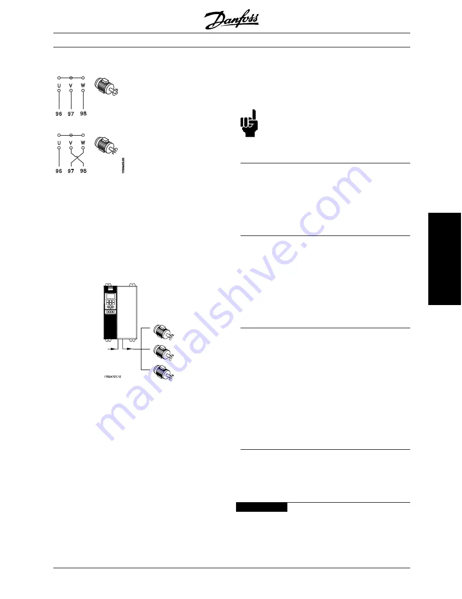
Direction of IEC motor rotation
The factory setting is for clockwise rotationwith the VLT
frequency transformer output connected as follows.
Terminal 96 connected to U-phase
Terminal 97 connected to V-phase
Terminal 98 connected to W-phase
The direction of rotation can be changed by switching
two phases in the motor cable.
■
Parallel coupling of motors
VLT 4000 VT is able to control several motors
connected in parallel. If the motors are to have
diffe-rent rpm values, the motors must have
different rated rpm values. Motor rpm is changed
simultaneously, which means that the ratio between
the rated rpm values is maintained across the range.
The total current consumption of the motors
is not to exceed the maximum rated output
current I
VLT,N
for the VLT AFD.
Problems may arise at the start and at low rpm values if
the motor sizes are widely different. This is because the
relatively high ohmic resistance in small motors calls for
a higher voltage at the start and at low rpm values.
In systems with motors connected in parallel, the
electronic thermal relay (ETR) of the VLT AFD cannot
be used as motor protection for the individual
motor. Consequently, additional motor protection
is required, such as thermistors in ground motor
(or individual thermal relays).
NOTE
Parameter 107
Automatic Motor Adaptation,
AMA
and
Automatic Energy Optimization, AEO
in parameter 101
Torque characteristics
cannot
be used motors are connected in parallel.
■
Motor cables
See
Technical data
for correct sizing of motor
cable cross-section and length.
Always comply with national and local regulations
on cable cross-sections.
■
Motor thermal protection
The electronic thermal relay in UL-approved AFD has
received UL-approval for single motor protection, as
long as parameter 117
Motor thermal protection
has
been set to ETR Trip and parameter 105
Motor current,
I
VLT,N
has been programmed for the rated motor current
(can be read from the motor nameplate).
■
Ground connection
Since the leakage currents to ground may be higher
than 3.5 mA, the AFD must always be grounded
in accordance with applicable national and local
regulations. In order to ensure good mechanical
connection of the ground cable, its cable cross-section
must be at least 8 AWG/10 mm
2
. For added
security, an RCD (Residual Current Device) may be
installed. This ensures that the AFD will cut out
if the leakage currents get too high.
■
Installation of 24 Volt external DC supply:
Torque: 0.5 - 0.6 Nm
Screw size: M3
No.
Function
35 (-), 36 (+)
24 V external DC supply
24 V external DC supply can be used as low-voltage
supply to the control card and any option cards
installed. This enables full operation of the LCP (incl.
MG.40.A4.22 - VLT is a registered Danfoss trademark
47
Installation