


•
•
•
•
5 Installation Guidelines
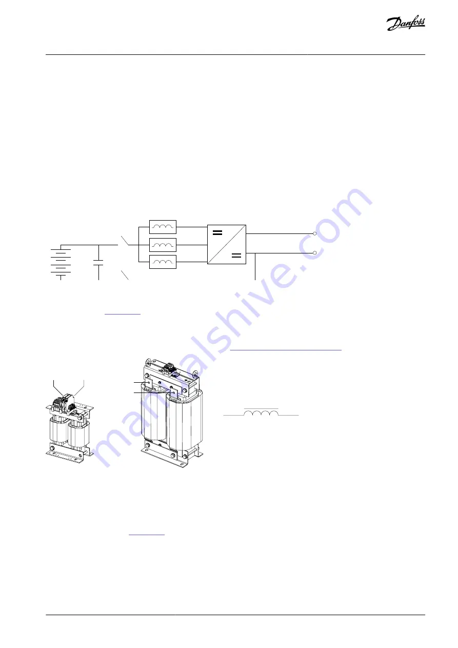
5.1 Cabling
The DC filter is connected between the DC/DC converter and the DC source. Three L-type inductors are required for a typical DC/DC
converter application. The order code for the listed L-type DC filters includes three 1-phase inductors.
For EMI reasons, keep the cable length between the DC source and DC/DC converter as short as possible. Sometimes, the parasitic
components of the source and cable can resonate with the DC filter inductors, causing instability in the control. The resonance can
be avoided by adding an external filtering capacitor (C) to the output of the DC filter. The formed LC filter resonance must be well
below the switching frequency.
To reduce the radiation of electromagnetic noise into the environment and to prevent malfunctions in the installation, use shielded
cables.
If unshielded cables are used, make sure that the installation minimizes the possibility of cross-coupling with other cables that are
carrying sensitive signals. This can be achieved, for example, by cable routing.
Follow the instructions for cable size selection for the DC/DC converter.
DC Source
DC/DC Converter
DC link
DC+
DC-
L
C
e3
0b
j3
52
.1
0
Illustration 2: DC Filter Connections
The L-type inductors have two winding poles connected in series. The terminals are at the top of the 1-phase inductors, and are
marked as shown in
10–30 A inductors have terminal connectors.
50–1150 A inductors have busbar terminals.
DC filter terminal sizes and mounting specifications are given in
7.6 Terminal and Torque Specifications
L
in
/L
out
L
in
/L
out
L
in
L
out
L
out
/L
in
L
out
/L
in
e3
0b
j4
95
.1
0
Illustration 3: DC Filter Terminals
5.2 Thermal Protection
Depending on requirements, the DC filter can be selected with built-in Pt100 temperature sensors or thermal relays (normal closed).
If temperature level monitoring is required, select the Pt100 type DC filter. The thermal relay type protection is used for indication of
alarm and fault limits of the DC filter. The temperature sensors are mounted in all three separate inductors. The wiring of the tem-
perature sensors is shown in
.
The option board OPT-BH is required for the Pt100 sensors. Each sensor is wired to its own channel. Thermal relay type sensors can
be connected to any digital input of the drive. One digital input is used for the alarm signal and another for the fault signal by wiring
the sensors in series. The auxiliary power input is the same for both the alarm and fault sensors.
Switching temperatures of the thermal relays depend on the DC filter type. See the datasheet of the DC filter for specific values. The
temperature limits are:
Alarm = 125–140 °C
Fault = 140–155 °C
AJ377845348678en-000101 / 172F4785 | 13
Danfoss A/S © 2023.01
Installation Guidelines
DC Filters
Design Guide
Содержание Vacon NXP
Страница 1: ...Design Guide DC Filters VACON NXP DC DC Converter drives danfoss com...
Страница 2: ......


