Danfoss MPCAN Скачать руководство пользователя страница 9

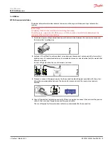
MPCAN receiver installation

The below information describes hazards to be aware of during installation and steps to locate the

receiver.

Risk of shock
Completely shut down the machine when installing the receiver.
Check the power supply and shut off the main switch to disconnect the interface cable between the
receiver and the machine's electrical box.

1. Find an easily accessible and clear location with a direct vision between the receiver's antenna and

the transmitter's working area.

7

8

9

10

11

CANL

12

GND

6

5

K4/ IN4

4

3

2

CANH

1

Vin

KS

TOP 2.2

KS

TOP 1.2

K3/ IN3

K1/ IN1

K2/ IN2

KS

TOP 1.1

KS

TOP 2.1

2. Optional: If it is difficult to achieve direct vision between the receiver's antenna and the transmitter's

working area, it is recommended to use an extended antenna in a clear location (only for models that

allow an antenna).
In areas of high vibration, the use of dampers is advised.

7

8

9

10

11

CANL

12

GND

6

5

K4/ IN4

4

3

2

CANH

1

Vin

KS

TOP 2.2

KS

TOP 1.2

K3/ IN3

K1/ IN1

K2/ IN2

KS

TOP 1.1

KS

TOP 2.1

3. Proceed to connect the power supply. Use the connection block diagram provided with the system,

where the correspondence between the transmitter maneuvers and the receiver's outputs are

detailed.

7

8

9

10

11

CANL

12

GND

6

5

K4/ IN4

4

3

2

CANH

1

Vin

KS

TOP 2.2

KS

TOP 1.2

K3/ IN3

K1/ IN1

K2/ IN2

KS

TOP 1.1

KS

TOP 2.1

4. Check if the electrical installation and verify if there's an option to connect the neutral or the ground

cable. In that case, don't forget to connect the ground cable.
The use of fireproof or flame retardant cables are recommended for the connection.

User Manual

MPCAN Receiver

Installation


©

 Danfoss | March 2022

BC292573933619en-000201 | 9

Содержание MPCAN

Страница 1: ...User Manual Remote Control MPCAN Receiver www danfoss com...

Страница 2: ...revisions Date Changed Rev March 2022 Updated safety instructions and technical descriptions 0201 January 2019 Rebranded to Danfoss Power Solutions 0101 User Manual MPCAN Receiver 2 Danfoss March 202...

Страница 3: ...detailed description 7 Installation Receiver installation 9 Input and output configuration 10 STOP category 3 PLe 10 Pinout 11 Troubleshooting MPCAN Receiver Faceplates 12 MPCAN400 900MHz LED troubles...

Страница 4: ...e brouillage et 2 l utilisateur de l appareil doit accepter tout brouillage radio lectrique subi m me si le brouillage est susceptible d en compromettre le fonctionnement MPCAN General Safety The foll...

Страница 5: ...use Always press STOP before plugging in tether cable if applicable Remove the Tether connection on the transmitter First if applicable Do not operate product when visibility is limited Make sure prod...

Страница 6: ...MPCAN dimensions Dimensions in mm 15 75 35 99 29 20 133 03 R 3 70 42 27 118 73 101 60 324 52 92 25 User Manual MPCAN Receiver Technical description 6 Danfoss March 2022 BC292573933619en 000201...

Страница 7: ...10 Internal fuse 7 5A MPCAN detailed description Technical data Specification Value Stop function 400 900 MHz Cat 3 PLd Stop Function 2 4 GHz Cat 4 PLe Ingress protection IP65 NEMA4 Frequency band ER...

Страница 8: ...uts 4 Proportional inputs N A Reponse time 100ms Maximum Total output current 7 5A Operating temperature range 20 C to 70 C 4 F to 158 F Storage Temperature Range 24h 25 C to 75 C 13 F to 167 F Storag...

Страница 9: ...is recommended to use an extended antenna in a clear location only for models that allow an antenna In areas of high vibration the use of dampers is advised 7 8 9 10 11 CANL 12 GND 6 5 K4 IN4 4 3 2 C...

Страница 10: ...ther at the same time The MPCAN includes a 7 5A internal fuse A1 A7 A8 A6 A5 IN1 IN2 IN3 IN4 Internal Vcc MPCAN STOP category 3 PLe Stop function is performed by two relays in series or parallel A10 a...

Страница 11: ...A3 A9 A4 CM NO STOP2 STOP1 NO CM MPCAN pinout 7 8 9 10 11 12 6 5 4 3 2 1 Pin Description 1 Vin 2 CANH 3 KSTOP 2 2 4 KSTOP 1 2 5 K4 IN4 6 K3 IN3 7 K1 IN1 8 K2 IN2 9 KSTOP 1 1 10 KSTOP 2 1 11 CANL 12 G...

Страница 12: ...el LED on DATA switched off Radio channel occupied by non Danfoss system Change transmitter s frequency channel DATA Green pulsing Receiving good frames OK ID LED off DATA LED on No valid ID Danfoss s...

Страница 13: ...Blue fast pulses System is starting establishing connection with radio and EEPROM Wait Blue continuous Waiting for transmitter communication coming from ACTIVE STOP Release STOP button and press STAR...

Страница 14: ...ON N A RELAY Green continuous STOP relay activated N A CANERR Red slow pulses CAN Error physical Layer Verify Connections Red double pulses One expansion has Stopped working Verify Expansion boards R...

Страница 15: ...anfoss Power Solutions US Company 2800 East 13th Street Ames IA 50010 USA Phone 1 515 239 6000 Danfoss Power Solutions Trading Shanghai Co Ltd Building 22 No 1000 Jin Hai Rd Jin Qiao Pudong New Distri...

Отзывы: