Instruction
INFOCAL 8
DEN-SMT/PL
VI.SH.L1.02
Danfoss District Enrgy
6
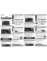
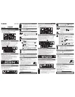
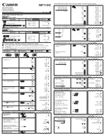
Once the calculator has been installed, the components (calculator,
volume measuring component and both temperature sensors) must
be sealed and the meter taken into operation.
Bleed the system until the flow rate display is steady.
Check the display for a plausible indication of flow rate and
temperatures.
7.0 Start-up operation
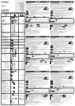
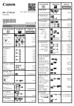
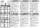
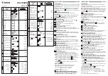
The energy calculator has two slots for expansion modules. The mod-
ules can be used and combined as shown in the table. The analogue
module needs both slots. Integrated radio is always possible. The
analog module occupies both positions.
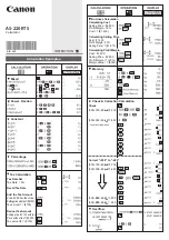
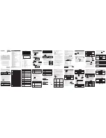
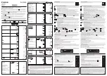
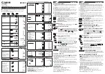
8.1 Installation of modules
1. Open the calculator by releasing the side fasteners
2. Lock the module into the appropriate slot and carefully connect
the pre-formed ribbon cable at both ends.
3. Close the lid and check the calculator for correct operation by
pressing the push button (loop 3). Renew the seal of the housing
lid if the calculator functions correctly.
The relevant ESD regulations (electrostatic discharge) must be
observed.
No liability is accepted for damage (especially to electronic circuits)
resulting from failure to comply with the ESD regulations.
These modules have no effect on consumption recording and can
be fitted retrospectively without damaging the verification mark.
interface / slot 2
n
o m
od
ul
e
M
-B
us
R
S2
32
R
S4
85
pu
lse
in
pu
t
L-
Bu
s
(fo
r e
xt
er
na
l
ra
di
o)
in
te
rf
ac
e / s
lo
t 1
no module
•
–
–
–
–
–
M-Bus
•
•
•
•
–
•
RS232
•
–
–
–
–
–
RS485
•
–
–
–
–
–
pulsse input
•
•
•
•
–
•
pulse output
•
•
•
•
•
•
pulse in-/
output
•
•
•
•
–
•
analogue
output
4...20mA
•
–
–
–
–
–
L-Bus
(for external
radio)
•
–
–
–
–
–
• combination is possible
– combination is not possible
* integrated radio is always possible
2
1
3
3
8.0 Expansion modules
1 Slot 1
2 Slot 2
3 Fixing clips