manualshive.com logo in svg
background image

Instruction  

INFOCAL 8

6.0  Power supply

INFOCAL 8 can be powered from lithium battery (11 or 16 years life-

time) or 230V AC / 24V AC mains unit supply.

Battery

3.6 V DC lithium battery is fitted in the standard version. The battery is 

not to be charged, replaced or short-circuited. Ambient temperatures 

below 35°C ensure the typical life of the battery.

Mains unit

24 VAC or 230 VAC power supply units can be changed to or retro-

fitted at any time. The cable is to be fuse at max. 6 A and protected 

against manipulation. Connect the cable according the labelling 

of the terminal. The power supply unit notifies the meter if mains 

voltage is present.

If the power supply fails, the backup battery (CR2032) provides the 

power supply for up to 1 year. The LCD readings (on pressing button) 

and the date and time are still updated, but none of the measuring 

functions work, incl. the flow rate measurement. Communication 

still functions over the optional M-Bus, RS485 and RS232 modules or 

the optical interface, but reduces the life of the backup battery. The 

radio function is switched off in the event of power supply failure.

Caution

Used batteries must be disposed of at suitable waste collection 

points.

Risk of explosion if battery is replaced by an incorrect type. 

Caution

It is strictly necessary to have protective safety cover installed 

at all times. 

Under no circumstances connect between the two phases 

otherwise the power supply unit will be destroyed.
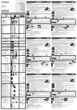
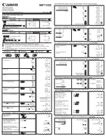
SONO 1500 CT

Calculator terminal

  Vcc (brown)*

9 (+)

Pulse (white)

10

GND (blue)

11 (-)

SONO 3500 CT

Calculator terminal

56

10

57 

11 (-)

white

blue

yellow

brown

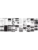
Wiring flow sensor SONO 1500 CT:

* Connect only if SONO 1500 CT with external supply

Wiring flow meter SONO 3500 CT:

(Typically connected to pulse output A)

Danfoss District Energy 


VI.SH.L1.02 


               DEN-SMT/PL

5

Содержание INFOCAL 8

Страница 1: ...ng personnel trained in the installation and use of electrical equipment and familiar with the Low Voltage Directive The specified absolute temp measuring range is 0 90 C 105 C 180 C The temperature range depends on calculator variant The exact temperature range is shown on the type plate The specified operating ambient conditions are 5 55 C max 93 rel humidity Protection class IP54 Ambient temper...

Страница 2: ... personnel Initial operation is to be carried out and recorded after installation For medium temperatures of more than 90 C or if Twater Tambient for application as cooling meter or heat meter with cooling tariff the calculator must be removed from the flow sensor and installed a sufficient distance away from heat sources A wall holder supplied with meter or a space holder optional is available fo...

Страница 3: ...5 or 90 angle The tip of the pocket must point in the opposite direction to the direction of flow and must be located in the middle of the pipe The temperature sensors must be sealed after installation in the pockets Connect the sensor cables to terminals as shown below For 2 wire connection to terminal 5 6 and 7 8 For 4 wire connection to terminal 1 5 6 2 and 3 7 8 4 Calculator type Sensor markin...

Страница 4: ...ication Chilled water application TH TC TC TH Flow meter connection with pulse input and if required with power supply at the terminals 9 Vcc 10 flow pulse 11 Gnd of the calculator Pulse frequency 200 Hz Pulse duration 3 msec Pulse rate in display Loop 3 INFO In0 Flow sensor connection Sensor marking External Vcc 3 6 V 9 Open collector 10 Ground 11 5 0 Pulse input volume pulses Calculator heating ...

Страница 5: ...ime are still updated but none of the measuring functions work incl the flow rate measurement Communication still functions over the optional M Bus RS485 and RS232 modules or the optical interface but reduces the life of the backup battery The radio function is switched off in the event of power supply failure Caution Used batteries must be disposed of at suitable waste collection points Risk of e...

Страница 6: ...propriate slot and carefully connect the pre formed ribbon cable at both ends 3 Close the lid and check the calculator for correct operation by pressing the push button loop 3 Renew the seal of the housing lid if the calculator functions correctly The relevant ESD regulations electrostatic discharge must be observed No liability is accepted for damage especially to electronic circuits resulting fr...

Страница 7: ...ve By Fixed Network For problematic radio installations shield the external radio module set can also be used 9 2 M Bus communication module The M Bus communication module is a serial interface for communi cation with external devices M Bus control centres e g IZAR CENT ER A number of meters can be connected to a control centre The module contains a 2 pole terminal strip with terminals marked 24 2...

Страница 8: ... A 3 VDC voltage is connected to the terminal and can be used as the supply for a flow sensor The pulse output has the same characteristics as pulse output 1 speci fied under 8 6 It is not however electrically isolated 9 8 Analogue output function module The module has 2 passive analogue output connections which are freely programmable using the IZAR SET software On the terminal strip the electric...

Страница 9: ...r Accounting date 1 previous year energy Accd 1L 2 4 Accounting date 2 Accounting date 2 energy Accd 2A 2 5 Accd 2 Future accounting date 2 2 6 Accounting date 2 previous year Accounting date 2 previous year energy Accd 2L 2 14 Accounting date 2 previous year Pulse input 2 Pulse input volume 2 Loop Sequence Window 1 Window 2 Window 3 3 Info loop 3 1 Current date Current time 3 2 SEC_Adr Secondary ...

Страница 10: ...ted by pressing the button The error code display appears again automatically if the button is not pressed for approx 4 minutes The error display disappears automatically as soon as the cause of the error has been cleared All errors present longer than 6 minutes are saved in the error log Error code Description C 1 Basic parameters saved in flash or RAM have been lost E 1 Temperature range outside...

Страница 11: ...Instruction INFOCAL 8 Danfoss District Energy VI SH L1 02 DEN SMT PL 11 ...

Страница 12: ...Instruction INFOCAL 8 VI SH L1 02 Produced by Danfoss A S 12 2014 ...

Отзывы: