Danfoss
ET4020 Crimp Machine Operator’s Manual
8 | © Danfoss ET4020 Crimp Machine Operator’s Manual | 2022.12.
AQ435956026217en-000101
Calibration
Must do Part I and Part II
WARNING : Maintain clear distance
from all moving parts.
The calibration procedure below will calibrate the Danfoss ET4020 crimp
machine to the original factory setting. While new machines are calibrated
at the factory and will be ready to use out of the crate, this procedure
should be followed if the crimp machine has been disassembled or has
had components replaced. The procedure requires the use of an FT1380-
200-M240 die cage, a TTC/Z Series -8 fitting and a TTC/Z Series -12 fitting.
1. CAUTION:
While in the calibration mode, follow the instructions
precisely and press the keys deliberately. If a mistake is made, the
calibration procedure must be started over from the beginning.
Part I
1.
Insert an FT1380-200-M240 die cage.
2.
Press the STORE and ENTER buttons simultaneously, then release. Both
button lights will now be illuminated and will remain so until the
calibration procedure is finished.
3.
Enter in the value of “100” using the keypad. (Don’t hit enter.)
4.
Center a TTC/Z Series -8 fitting (without a hose) in the die cage,
holding the socket or fitting in place with a pencil or other suitable
tool. Crimp the socket by depressing the crimp switch until the
machine retracts by itself, indicating a completed cycle. Allow the
crimp ring to return to the “soft retract” position.
5.
Using a set of calipers, measure the crimp diameter. The preferred
method is to use the average of the four pairs of indentations.
6.
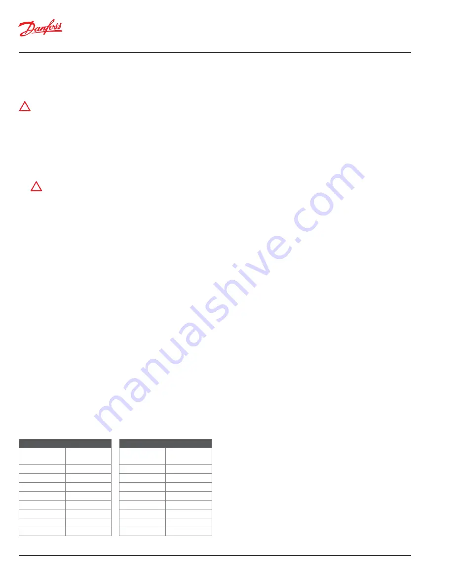
Locate the crimp diameter in Table A, below. Using the keypad, enter
in the three-digit Display Reading that corresponds to the Crimp
Diameter.
Note:
If your Crimp Diameter falls between the numbers shown in Table A,
simply determine or interpolate the Display Reading, since the numbers are
a direct ratio.
Part II
1.
Enter in the value of “400” using the keypad. (Don’t hit enter.)
2.
Center a TTC/Z Series -12 fitting (without a hose) in the die cage,
holding the socket or fitting in place with a pencil or other suitable
tool. Crimp the socket by depressing the crimp switch until the
machine retracts by itself, indicating a completed cycle.
3.
Repeat steps 5 and 6 at left, except use Table B instead of Table A for
the -12 fitting.
4.
After the three-digit Display Reading is entered, the machine will
automatically exit the calibration mode.
Calibration Example
Part I
Crimp a TTC/Z Series -8 fitting and measure the four crimp diameters
around the socket. For example, the diameters measure .942, .946, .945 and
.945 inches, to obtain the average diameter, add the four diameters and
divide that sum total by 4.
(.942+.946+.945+.945)/4 = (3.778 )/4= 0.9445 = 0.945
(round to nearest thousandth)
Look at the Crimp Diameter column in Table A and find your average
diameter. If it falls between two numbers, as this one does, interpolate the
desired setting. In this case, you would enter 045. If your crimp diameter
was .940, you would enter 040; if it was .942, you would enter 042.
Part II
Crimp a TTC/Z Series -12 fitting and measure the four crimp diameters
around the socket. This time, let’s say that the diameters measure 1.247,
1.249, 1.249 and 1.248 inches. Average the measures by adding the four
diameters and dividing that sum total by 4.
(1.247+1.249+1.249+1.248)/4 = (4.993)/4 = 1.24825 = 1.248
(round to nearest thousandth)
Look at the Crimp Diameter column in Table B and find your average
diameter. If it falls between two numbers, as this one does, interpolate the
desired setting. In this case, you would enter 348. If your crimp diameter
was 1.250, you would enter 350; if it was 1.249, you would enter 349.
!
!
Table A for -8
Crimp Diameter
Display
Reading
0.940
040
0.950
050
0.960
060
0.970
070
0.980
080
0.990
090
1.000
100
1.010
110
Table B for -12
Crimp Diameter
Display
Reading
1.240
340
1.250
350
1.260
360
1.270
370
1.280
380
1.290
390
1.300
400
1.310
410


