


AKD 2800
■
Special conditions
■
Aggressive environments
As all other electronic equipment, a frequency
converter contains a number of mechanical and
electronic components, which to a varying extent
are vulnerable to environmental impact.
Consequently, the frequency converter is
not to be installed in environments, where
liquids, particles or gases are in the air that
would impact and damage the electronics. Unless the
necessary measures are taken to protect the frequency
converter, there is a risk of stoppages, which reduce
the service life of the frequency converter.
Liquids can be carried through the air and condense
in the frequency converter. In addition, liquids may
facilitate galvanic corrosion of components and metal
parts. Steam, oil and brine may cause corrosion of
components and metal parts. In these areas, it is
recommended to fit units in cabinets. As a minimum,
cabinets should be enclosure IP 54.
Particles in the air, such as dust particles, may lead
to mechanical, electrical and thermal faults on the
frequency converter. Typical indicators that there
are too many particles in the air are dust particles
around the frequency converter fan. In very dusty
areas, cabinet fitting of units is recommended. As a
minimum, cabinets should be enclosure IP 54.
Aggressive gases, such as sulphur, nitrogen and
chlorine compounds, together with high humidity and
temperature, facilitate possible chemical processes on
the components of the frequency converter. These
chemical processes quickly impact and damage
the electronics. In these areas, cabinet fitting with
fresh-air circulation in the cabinet is recommended,
thereby ensuring that aggressive gases are kept
away from the frequency converter.
NB!:
Fitting of frequency converters in aggressive
environments increases the risk of stoppages,
in addition to considerably reducing the
service life of the unit.
Before the frequency converter is installed, it must be
checked whether there are liquids, particles or gases
in the air. This can be done by looking at existing
installations in the same environment. Typical indicators
of harmful airborne liquids are water or oil on metal parts
or corrosion of metal parts. Too many dust particles are
typically observed on top of installation cabinets and on
existing electrical installations. Indicators that there are
aggressive gases in the air are copper rails and cable
ends that are black on existing electrical installations.
■
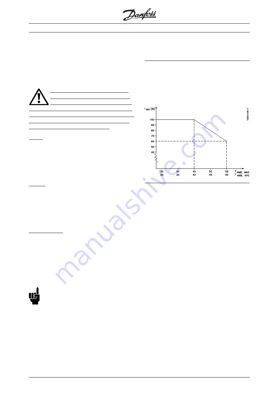
Derating for ambient temperature
The ambient temperature (T
AMB,MAX
) is the maximum
temperature allowed. The average (T
AMB,AVG
) measured
over 24 hours, must be at least 5 °C lower. If the
frequency converter operates at temperatures above 45
°C, a derating of the rated output current is necessary.
■
Galvanic Isolation (PELV)
PELV (Protective Extra Low Voltage) insulation is
achieved by inserting galvanic isolators between the
control circuits and circuits that are connected to the
mains potential. The frequency converter is designed
to meet the requirements for protective separation
by means of having the necessary creepage and
clearance distances. These requirements are described
in standard EN 50 178. It is also a requirement
that the installation is carried out as described in
local/national regulations regarding PELV.
All control terminals, terminals for serial communication
and relay terminals are safely separated from the
mains potential, i.e. they comply with the PELV
requirements. Circuits that are connected to control
terminals 12, 18, 19, 20, 27, 29, 33, 42, 46, 50,
53, 55 and 60 are galvanically connected to one
another. Serial communication connected to fieldbus
is galvanically insulated from the control terminals,
although this is only a functional insulation.
The relay contacts on terminals 1 - 3 are insulated
from the other control circuits with reinforced/double
isolation, i.e. PELV is observed for these, even though
there is mains potential at the relay terminals.
The circuit elements described below form the safe
electric separation. They fulfill the requirements
for reinforced/double insulation and associated
testing pursuant to EN 50 178.
MG.28.H2.02 -
62