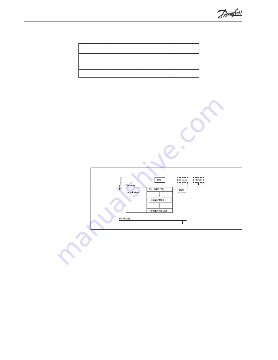
A router table may have a varying number of lines. In the example shown below there is one line.
The table always consists of four fi elds
when operation takes place with AKA 21:
“Lower Limit”, “Upper Limit”, “Port No.”, and “Address”.
1
2
3
4
Lower limit
Upper limit
Port No.
Address/
Telephone no/
IP Address
1
1
2
In principle the fi elds indicate the following:
Fields 1 and 2: a group of units capable of receiving / sending a messa ge.
Field 3: the direction in which the message is to be sent.
Field 4: indicates the unit which is the next receiver of the message. From this position the following
may happen:
1) The message is sent on to another network (in which case a new router has to be
established with a new port and a new address).
2) The message is sent to a PC on the RS 232 output.
Below follows a more detailed description of the fi elds.
Field 1 + 2: “Lower Limit”, “Upper Limit”
These are network no. which together indicate an interval range between a lower and an
upper network limit.
Field no. 3: “Port No”.
There are two ports through which datagrams can be directed. “Port No.” indicates the
direction in which the datagram has to be transmitted.
Port 1:
Access to units connected to DANBUSS
Port 2:
Access to either a PC, a modem or a TCP/IP server.
Field 4: “Address”
The contents depend on what was specifi ed in the fi eld “Port No.” :
If “Port No.” = 1 (DANBUSS):
An address is indicated for the next receiver of the datagram. This may either be the
fi nal receiver for whom the datagram was intended, or it may be the address of another
AKA 245, say, a modem gateway that has to re-transmit the datagram.
If “Port No.” = 2 (RS 232):
At connection to a PC no address has to be entered, as only one PC can be connected.
In operation via the control panel the menu system will automatically detect this, and it
will not be possible to key an address.
On modem gateway or TCP/IP server you key the telephone number (in the fi eld “Add-
ress”) that is to be called or the actual IP address.
Appendix A - continued
34
Manual RS8DT102 © Danfoss 09/2004
AKA
245
Содержание AKA 245
Страница 1: ...REFRIGERATION AND AIR CONDITIONING Gateway AKA 245 Manual...
Страница 41: ...AKA 245 Manual RS8DT102 Danfoss 09 2004 41...
Страница 42: ...42 Manual RS8DT102 Danfoss 09 2004 AKA 245...
Страница 43: ...AKA 245 Manual RS8DT102 Danfoss 09 2004 43...


