background image

Electronic Torque Limiting Control

Repair

Disassembly, inspection and reassembly steps are the same as the steps in the previous topic (Electric

Controls). This includes repair of the spools and plugs.

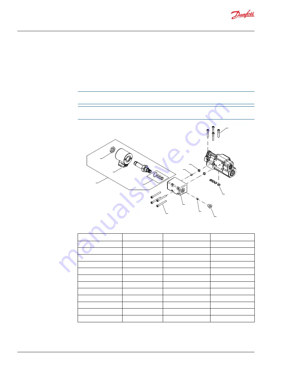
The solenoid (C155), nut (QC125), and O-rings (QC120) for the valve are available as separate repair

parts. The valve is only available as a complete assembly (QC150).

If it is necessary to remove the orifice (H020), use a 3 mm internal hex wrench. Torque it to 2.7 Nm [24

in-lb] when it is installed in the manifold.

P108790

QC125

* Included in overhaul seal kit Q210

C155

QC150

QC120

C154

C149

C151

C152

H020

C153

*C200

C300

Item

Description

Wrench size

Torque

C149

Orifice

3 mm internal hex

2.7 Nm [24 in-lb]

C151

Screws

6.4 Nm [4.7 lbf-ft]

C152

Manifold

-

-

C153

Plug

5 mm internal hex

12 Nm [8.9 lbf-ft]

C154

O-ring

-

-

C155

Solenoid

-

-

C200

O-rings

-

-

C300

Screws

6.4 Nm [4.7 lbf-ft]

QC120

O-rings

QC125

Nut

8.7 Nm [6.4 lbf-ft]

QC150

Valve assembly

27.7 Nm [20.4 lbf-ft]

H020

Manifold orifice

3 mm internal hex

2.7 Nm [24 in-lb}

Service Manual

Series 45 E Frame Open Circuit Pumps

Minor repair


36 | 

©

 Danfoss | September 2016

AX00000024en-US0401

All manuals and user guides at all-guides.com

all-guides.com

Содержание 45 E Frame Series

Страница 1: ...Service Manual Open Circuit Axial Piston Pumps Series 45 E Frame powersolutions danfoss com All manuals and user guides at all guides com a l l g u i d e s c o m ...

Страница 2: ...301 August 2015 Danfoss Layout 0300 October 2012 add new control types AG November 2010 new last page AE February 2010 fix Osaka address AD March 2008 add displacement limiter specs AC March 2005 First edition A Service Manual Series 45 E Frame Open Circuit Pumps 2 Danfoss September 2016 AX00000024en US0401 All manuals and user guides at all guides com ...

Страница 3: ...xiliary mounting pads 12 Input shafts 13 Control options 13 General 13 PC control 13 LS control 14 Electric Proportional Controls 15 Electric On Off Controls 15 Electronic Torque Limiting Controls ETL 16 PLUS 1 Compliance 16 Electric Torque Limiting Control Principle 16 Pressure measurement Required tools 18 Port locations and gauge installation 18 Initial Start Up Procedures General 19 Start up p...

Страница 4: ...30 Inspection 31 Reassembly 32 Electric Controls 34 Disassembly 34 Inspection 34 Reassembly 35 Electronic Torque Limiting Control 36 Repair 36 Angle Sensor 37 Removal 37 Inspection 37 Reassembly 38 Servo Control Orifice 39 Plug and fitting sizes and torques 40 Service Manual Series 45 E Frame Open Circuit Pumps Contents 4 Danfoss September 2016 AX00000024en US0401 All manuals and user guides at al...

Страница 5: ...ety precautions Always consider safety precautions before beginning a service procedure Protect yourself and others from injury Take these general precautions whenever servicing a hydraulic system Unintended machine movement W Warning Unintended movement of the machine or mechanism may cause injury to the technician or bystanders To protect against unintended movement secure the machine or disable...

Страница 6: ...ion Parallelism specification Torque specification External hex head Press in press fit Internal hex head Pull out with tool press fit Torx head Cover splines with installation sleeve O ring boss port Pressure measurement gauge location or specification The symbols above appear in the illustrations and text of this manual They are intended to communicate helpful information at the point where it i...

Страница 7: ...lock valve plate and slipper swashplate interfaces for lubrication and cooling Case drain ports are provided to return this fluid to the reservoir The volume of fluid displaced into the system circuit is controlled by the angle of the swashplate The swashplate is forced into an inclined position into stroke by the bias piston and spring The servo piston opposes the action of the bias piston and sp...

Страница 8: ...demand for flow in the system and communicates this to the pump control by means of a hydraulic signal load sense signal The pump will provide as much flow to the system as it demands while limiting the maximum pressure Therefore flow and pressure in the system are compensated to meet requirements Full available flow is a function of pump displacement operating speed and efficiency Refer to Series...

Страница 9: ...chnical specifications Features and options Feature Unit Model E100B E130B E147C Maximum Displacement cm in 100 6 10 130 7 93 147 8 97 Flow at rated speed theoretical l min US gal min 245 64 7 286 75 6 309 81 6 Input torque at maximum displacement theoretical N m bar lbf in 1000 psi 1 592 972 2 069 1263 2 340 1428 Mass moment of inertia of internal rotating components kg m slug ft 0 0128 0 0094 0 ...

Страница 10: ... Thrust in Tin out Tout N lbf 2846 640 1735 390 2113 475 Thrust out Tout 7740 1740 6672 1500 7117 1600 Bearing life at 140 bar 2030 psi B10 hours 77 200 32 700 21 600 at 210 bar 3045 psi 19 800 8400 5500 at 260 bar 3770 psi 9700 4116 2700 at 310 bar 4495 psi 5400 2300 Mounting flange load moments Vibratory continuous N m lbf in 1920 17 000 Shock max 6779 60 000 1 Input speeds are valid at 1 bar ab...

Страница 11: ... 1 Intermittent cold start 40 C 40 F Continuous 82 C 180 F Maximum 2 104 C 220 F 1 Hydraulic fluid viscosity must be maintained within the prescribed limits 2 As measured at the hottest point in the system e g drain line Fluid viscosity Viscosity limits Rating mm2 s cSt SUS ν continuous minimum 9 58 maximum 110 500 ν intermittent minimum 6 4 47 maximum cold start 1000 4700 Filtration Required clea...

Страница 12: ... older models 100 cc 6 5 cc rev 0 397 in rev 130 cc 147 cc Displacement limiter older models P104 046 Auxiliary mounting pads Auxiliary mounting pads are available for all radial ported Series 45 pumps These pads are typically used for mounting auxiliary hydraulic pumps Since the auxiliary pad operates under case pressure you must use an O ring to seal the auxiliary pump mounting flange to the pad...

Страница 13: ...ump control depending on conditions in the system circuit sets swashplate angle by metering system pressure to the servo piston Cross section pump P104 048 1 2 3 Bias spring and servo piston set swashplate position PC control The PC control design maintains a constant pressure in the hydraulic circuit as flow varies The PC control modulates pump flow accordingly to maintain system pressure at the ...

Страница 14: ...ing sets the threshold of operation LS setting Because the swashplate is biased to maximum angle the pump attempts to deliver full flow to the hydraulic system When the flow being delivered exceeds demand the pressure delta across the ECV is great enough to overcome spring force and shift the LS spool porting system pressure to the servo piston The pump de strokes reducing flow until the delta acr...

Страница 15: ...ectric Proportional Control Principle The Electric Proportional Control consists of a proportional solenoid integrated into a Remote Pressure Compensated control This control allows the pump to be operated at any pressure limit between the Load Sense and Pressure Compensation settings by varying the current sent to the solenoid Electric On Off Controls PLUS 1TM Compliance All Series 45 Electric co...

Страница 16: ... this Series 45 control is PLUS 1 compliant PLUS 1 compliance blocks are available on the Danfoss website within the PLUS 1 Guide section Electric Torque Limiting Control Principle The Electronic Torque Limiting control consists of a normally closed proportional relief valve PRV integrated into a Pressure Compensated Load Sensing control This control operates as a PC LS control with the additional...

Страница 17: ...nsidered constant the pump torque can be limited when pump displacement is known and pump pressure is controlled As pump displacement increases the pump outlet pressure can be limited using the PRV to result in a constant torque limit Pump outlet pressure is equal to the load sense pressure which is limited with the PRV plus the margin pressure setting of the pump Service Manual Series 45 E Frame ...

Страница 18: ...0 300 bar 0 5000 psi 9 16 18 O ring fitting M4 Servo pressure 0 300 bar 0 5000 psi 9 16 18 O ring fitting L1 L2 Case drain 0 300 bar 0 5000 psi 1 1 16 12 O ring fitting X1 LS signal 0 300 bar 0 5000 psi 7 16 20 O ring fitting tee into LS signal line Gauge port locations L1 X M4 X B X S M2 S B L2 M1 Legend B Main pressure line S Suction line L1 L2 Case drain lines X Load sensing pressure port M1 CW...

Страница 19: ...operly tightened fittings and be certain it is free of restrictions and air leaks 5 To ensure the pump stays filled with oil install the case drain line in the upper most case drain port 6 Install a gauge at the system pressure gauge port to monitor system pressure during start up Follow recommendations in the vehicle machine operator s manual for prime mover start up procedures 7 While watching t...

Страница 20: ... and filter per the vehicle machine manufacturer s recommendations or at these intervals Change the fluid more frequently if it becomes contaminated with foreign matter dirt water grease etc or if the fluid is subjected to temperature levels greater that the recommended maximum Dispose of used hydraulic fluid properly Never reuse hydraulic fluid Change filters whenever the fluid is changed or when...

Страница 21: ...tting Refer to the Adjustments chapter Check LS control signal pressures Incorrect LS signal will not allow pump to operate correctly Inspect system to ensure that proper LS signal transmit to pump Internal system leaks Worn internal parts don t allow the pump to operate properly Refer to Authorized Service Center for required repair Hydraulic fluid viscosity above acceptable limits Hydraulic flui...

Страница 22: ...chieving full stroke Adjust PC and LS setting Refer to the Adjustments chapter Check pump inlet pressure vacuum High inlet vacuum causes low output flow Correct inlet pressure conditions Check input speed Low input speeds decrease flow Adjust input speed Check pump rotation Incorrect rotational configuration causes low flow Use pump with appropriate rotational configuration Pressure or flow instab...

Страница 23: ...ion may interfere with movement of the PC spool Clean PC control components take appropriate action to eliminate contamination High inlet vacuum C Caution High inlet vacuum causes cavitation which can damage internal pump components Item Description Action Check fluid temperature Low temperature increases viscosity High fluid viscosity causes high inlet vacuum Allow system to warm up before operat...

Страница 24: ...mal operating temperature Operate a hydraulic function to its full extension loading the pump at maximum pressure and zero flow 3 Loosen the PC set screw and turn the PC adjusting plug until the desired setting is indicated on the pressure gauge at port M1 or M2 1 Clockwise rotation increases pressure counterclockwise rotation decreases approximate gain 42 bar 610 psi per turn If the pressure does...

Страница 25: ...68 N m 25 50 lbf ft P104053 0 10 bar 0 145 psi 7 8 14 54 136 N m 40 100 lbf ft Case drain port L1 PC set screw 6 mm PC adjusting plug Service Manual Series 45 E Frame Open Circuit Pumps Adjustments Danfoss September 2016 AX00000024en US0401 25 All manuals and user guides at all guides com ...

Страница 26: ...Loosen the LS set screw While watching the pressure gauges turn the LS adjusting plug until the desired pressure differential between port M1 or M2 and port X is achieved 1 Clockwise rotation increases the setting counterclockwise rotation will decrease it approximate gain 17 bar 250 psi per turn 1 The LS setting is a differential pressure Subtract pilot pressure at port X from system pressure at ...

Страница 27: ...uge locations shown Displacement Limiters E Frame open circuit pumps are available with an optional adjustable displacement limiter This adjustable stop limits the pump s maximum displacement Setting range E100B 40 to 100 cm 2 44 to 6 1 in E130B 70 to 130 cm 4 27 to 7 93 in E147C 87 to 147 cm 5 31 to 8 97 in Displacement per turn E100B 8 4 cm rev 0 51 in rev E130B 8 4 cm rev 0 51 in rev E147C 8 4 ...

Страница 28: ...oss section P104 003 Dimensions P108 470E 304 11 969 302 7 max 11 92 Service Manual Series 45 E Frame Open Circuit Pumps Adjustments 28 Danfoss September 2016 AX00000024en US0401 All manuals and user guides at all guides com ...

Страница 29: ... or contamination Polish the sealing area on the shaft if necessary 2 Lubricate the lip of the new shaft seal with clean hydraulic fluid Place a protective sleeve over the shaft end to prevent damage to the seal during installation 3 Keeping the seal perpendicular to the shaft press the new seal into the housing just far enough to clear the retaining ring groove Install seal with the cupped side t...

Страница 30: ...N m 67 82 lbf ft P104357 h9 16inch t37 50 N m 27 37 lbf ft Installation 1 Lubricate new O ring J090 with petroleum jelly Install the pad adapter to the endcap 2 Install the 4 screws J100 and torque to 47 5 61 N m 35 45 lbf ft 3 Install the drive coupling J140 if present 4 Install shipping cover with seal J120 or auxiliary pump with O ring customer supplied C Caution Shipping cover is intended only...

Страница 31: ... and C112 LS spool from the control housing discard the O ring Note orientation of the spool for reassembly Control assembly C118 C118B C118B C118A C114 C115 C113 C112 C104 C103 C132 C133 C105 C106 C106A C135 C134 C138A C138 C102 C200 C103A C104A E101226 C300 3 16inch 10 8 13 5 N m 8 10 lbf ft 3 16inch 10 8 13 5 N m 8 10 lbf ft 3 16inch 10 8 13 5 N m 8 10 lbf ft 3 16inch 10 8 13 5 N m 8 10 lbf ft ...

Страница 32: ...ool C112 spherical end first into the LS bore Using a new O ring C105A or C106A install the plug C105 or C106 Torque the plug C105 or C106 to 10 8 13 5 N m 8 10 lbf ft For PC only controls skip steps 15 through 17 4 Using a new O ring C104A install the plug C104 Torque the plug to 10 8 13 5 N m 8 10 lbf ft 5 Place the two LS springs C134 C135 onto the spring guide C113 and install into the LS bore...

Страница 33: ... 8 10 lbf ft 3 16inch 10 8 13 5 N m 8 10 lbf ft 3 16inch 10 8 13 5 N m 8 10 lbf ft 3 16inch 10 8 13 5 N m 8 10 lbf ft 6 mm 7 5 10 8 N m 5 5 8 lbf ft 4 mm 5 4 7 5 N m 4 5 5 lbf ft C105A LS control shown parts C104 through C106 and C112 through C118 are not used on PC control Service Manual Series 45 E Frame Open Circuit Pumps Minor repair Danfoss September 2016 AX00000024en US0401 33 All manuals an...

Страница 34: ...electric control manifold Control disassembly P108 668E G020 G030 C200 C102 C103 C132 C112 C104 C300 C125 C155 C150 C149 C154 C152 C151 C113 C115 C133 C135 C114 C118 C134 C138A C138 C153 Inspection 1 Inspect the adjusting plugs for wear at the tips and where they contact the springs replace as necessary 2 Inspect the springs and spring guides for wear or damage replace as necessary 3 Carefully ins...

Страница 35: ... m 18 30 in lb 8 Install the cartridge valve C150 into the electric control manifold C152 Torque to 25 8 28 5 N m 19 21 lbf ft DO NOT OVERTORQUE the cartridge valve 9 Install the electric solenoid C155 and solenoid coil nut C125 Torque to 6 8 9 5 N m 5 7 lbf ft 10 Install plug C153 Torque the plug to 10 8 13 5 N m 8 10 lbf ft 11 Using petroleum jelly to retain them install the two interface O ring...

Страница 36: ...in the manifold P108790 QC125 Included in overhaul seal kit Q210 C155 QC150 QC120 C154 C149 C151 C152 H020 C153 C200 C300 Item Description Wrench size Torque C149 Orifice 3 mm internal hex 2 7 Nm 24 in lb C151 Screws 6 4 Nm 4 7 lbf ft C152 Manifold C153 Plug 5 mm internal hex 12 Nm 8 9 lbf ft C154 O ring C155 Solenoid C200 O rings C300 Screws 6 4 Nm 4 7 lbf ft QC120 O rings QC125 Nut 8 7 Nm 6 4 lb...

Страница 37: ...r scratch seal area Right side P108840 K105 K115 K185 K175 K265 K195 Item Description Wrench size Torque K105 Magnet carrier K115 Carrier screws 4 5 Nm 3 35 lbf ft K175 O ring K185 Locating dowels K195 Screws 5 9 Nm 4 35 lbf ft K265 Housing Inspection 1 Carefully examine the angle sensor housing for mechanical damages cracks or scratched surfaces 2 Check the angle sensor connector for breaks pin d...

Страница 38: ...the screws to 4 5 Nm 3 3 lbf ft W Warning Used magnet carrier screws may loosen and lead to premature failure Ensure that new screws with locking compound are utilized 2 Install the locating dowels K185 into the dowel holes 3 Lubricate new O ring K175 with petroleum jelly Install the O ring to the angle sensor housing K265 first 4 Install angle sensor housing K265 with O ring K175 to housing with ...

Страница 39: ...ical end first into the PC bore Install plug C103 Torque the plug to 10 8 13 5 N m 8 10 lbf ft 7 Using petroleum jelly to retain them install the four O rings C200 in the recesses on the control housing 8 Install the control assembly onto the endcap using four screws C300 Torque the screws to 5 4 7 5 N m 4 5 5 lbf ft Torque screws in a criss cross pattern and re torque the first screw to ensure pr...

Страница 40: ...nd torques K040 1 1 16 inch 9 16 inch 95 135 N m 70 100 lbf ft J040 9 16 inch 1 4 inch 20 5 27 N m 15 20 lbf ft J042 9 16 inch 1 4 inch 36 50 N m 27 37 lbf ft L020 3 4 inch 5 16 inch 41 95 N m 30 70 lbf ft P104060 J041 9 16 inch 1 4 inch 20 5 27 N m 15 20 lbf ft K070 1 1 16 inch 9 16 inch 95 135 N m 70 100 lbf ft Service Manual Series 45 E Frame Open Circuit Pumps Minor repair 40 Danfoss September...

Страница 41: ...Service Manual Series 45 E Frame Open Circuit Pumps Danfoss September 2016 AX00000024en US0401 41 All manuals and user guides at all guides com a l l g u i d e s c o m ...

Страница 42: ...Service Manual Series 45 E Frame Open Circuit Pumps 42 Danfoss September 2016 AX00000024en US0401 All manuals and user guides at all guides com ...

Страница 43: ...Service Manual Series 45 E Frame Open Circuit Pumps Danfoss September 2016 AX00000024en US0401 43 All manuals and user guides at all guides com ...

Страница 44: ...mark Phone 45 7488 2222 Danfoss Power Solutions US Company 2800 East 13th Street Ames IA 50010 USA Phone 1 515 239 6000 Danfoss Power Solutions Trading Shanghai Co Ltd Building 22 No 1000 Jin Hai Rd Jin Qiao Pudong New District Shanghai China 201206 Phone 86 21 3418 5200 Danfoss can accept no responsibility for possible errors in catalogues brochures and other printed material Danfoss reserves the...

Отзывы: