background image

Part NO: 212-0024WB 

16 

July 30th, 2019 


D & R Electronics warrants its new products to be free from defects in material and workmanship, un-
der normal use and service for a period of one year on parts replacement. 
This warranty applies only to original purchasers acquiring the product directly from D&R Electronics, 
or its authorized dealers. Warranty will not be recognized without proof of purchase or bill of sale. 
This warranty is not transferable. 
The warranty begins on the date of delivery to the first user/purchaser. 
This warranty shall not apply to products which must be repaired due to normal wear and tear, negli-
gence, improper installation, abuse, misuse, or which have been altered or modified at a facility other 
than D & R Electronics, or its authorized depot centers. 
Units proved to be defective within the warranty period, based on an examination by D&R Electronics, 
will be replaced or repaired at D & R Electronics’ option. This warranty does not cover travel expenses 
or labor charges for removal or installation.  
Lamps, flash tubes, batteries or other items considered consumables are not covered under warranty. 
This warranty is in lieu of all other express warranties. D&R Electronics makes no warranties, ex-
pressed or implied, other than the express warranties contained herein. 

WARRANTY 

PRODUCT RETURN POLICY 

In order to provide you with faster service, product returns for repair or replacement, must have a 

Re-

turn Goods Authorization Number (RGA number)

. Please contact our  company to obtain a RGA 

number before you return the product to D & R ELECTRONICS. Write the RGA number clearly on the 
package. Be sure you use sufficient packing materials to avoid damage to the product being returned 
while in transit. 
D & R ELECTRONICS assumes no responsibility or liability for expenses incurred for the removal 
and/or the installation of products requiring service and/or repair. Repairing or replacing product is at 
the discretion of D & R ELECTRONICS.  

CANADA 
8820 George Bolton Pkwy. 
Bolton, Ontario L7E 2Y4 
Tel: (905) 951-9997 
Fax: (905) 951-0019 


USA 

2299 Kenmore Avenue  

Building 3, Doors 11-14 

Buffalo, New York 14207          

Toll Free: 1-800-538-7338 


www.dandrelectronics.com 

D&R ELECTRONICS Co. LTD. 

Содержание PDU42WB

Страница 1: ...able of Contents Applicable Models 2 Introduction 2 General Warnings 3 Unpacking Pre Installation Check 3 Installation Mounting 4 Wiring and Setup Instructions 4 Output Fuse Combinations 6 Timed Modes Of Operation 12 Maintenance 13 Parts List 13 Troubleshooting 14 Product Specifications 15 Warranty 16 ...

Страница 2: ...n requirements These output features have the following characteristics 1 Constant Battery Outputs There are 6 output connections each with individual fuses that are on at all times providing the PDU is connected to the battery 2 Ignition Controlled Outputs The 6 output power connections also individually fused provide 12V output while the vehicle ignition is on Power will be immediately turned of...

Страница 3: ...ut performance of vehicle sys tems 6 Placement of control switches must be so as to provide convenient reach for the opera tor without loosing eye contact with the road 7 Emergency warning devices require high electrical voltages and or currents Properly connect and ground all circuits Shorting or improper grounding of this device may caused personal injuring vehicle damage or both 8 All operators...

Страница 4: ...eration or turns 2 Be sure to mount unit through the steel of the vehicle Avoid mounting through plastic or other non structural materials 3 POINT OF INSTALLATION MUST NOT INTERFERE WITH DEPLOYMENT OF VEHICLE AIR BAGS 4 D R Electronics recommends this and any of our other products be installed by quali fied professionals Warning Mounting the PDU unit The PDU42WB may be mounted anywhere inside the ...

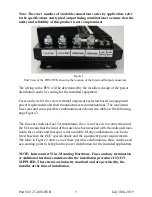
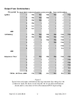
Страница 5: ...aximum fuse sizes and some possible combinations are shown in a table on the following page Figure 2 The fuses are indicated as 15A maximums the x is no fuse or no connection and the N A means that the limit of that area has been reached with the indicated max imum fuse values and that spot is not available Many combinations can be de rived based on the PDU specifications and the equipment power r...

Страница 6: ...WB Terminal block outputs showing some possible fuse combinations Ignition 1 15A 15A 15A 15A x 15A 2 15A 15A 15A x x x 3 15A 15A x x x x 4 15A x x x x x 5 N A x x x x x 6 N A x x x x x AND 12V Battery 1 15A 15A 15A 15A 15A 15A 2 15A 15A 15A 15A 15A x 3 x x 15A 15A 15A x 4 x x x 15A 15A x 5 x x x x 15A x 6 x x x x N A x AND Outputs on Timer 1 x 15A 15A 15A 15A 15A 2 x x x x x 15A 3 x x x x x 15A 4 ...

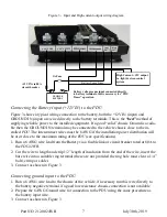
Страница 7: ...usible link or circuit breaker rated at 80A to the PDU42WB 2 Cut the wire to length and strip 1 2 length of insulation from the end of the wire insert the bare wire into a suitable ring terminal these are not provided the ring hole must clear a 1 4 bolt crimp or solder 3 Connect as shown in Figure 3 Connecting ground input to the PDU 1 Run a 6 AWG wire lead to the chassis of the vehicle if necessa...

Страница 8: ... battery should be fused and located as close as possible to the POSITIVE battery terminal We recommend a 1A fuse inside an inline weather resistant fuse holder be used Connecting high Current AMP power output from the PDU The PDU supplies a single high current 12V OUT output which may be used to power a high current device such as a light bar this output uses the same style of power connector as ...

Страница 9: ... PDU To activate the ignition control and timed outputs feature the PDU must receive a control sig nal from the vehicle 1 The installer must locate the ignition output from the vehicles wiring harness and run an 18 AWG wire from this point to the ignition input IGN IN on the PDU Care must be taken to connect the correct ignition control wire from the vehicle wiring har ness some of the newer vehic...

Страница 10: ...tions to and from the PDU are completed the output fuses can be installed according to the required rating of the connected equipment The PDU accepts a standard Automotive Blade ATO ATC Type fuses each fuse location has an LED indicator to show that the fuse is in place and working The LED indicator will glow RED if the fuse is GOOD otherwise it will be off Setting The Time Delay on Timed Outputs ...

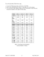
Страница 11: ...tches This will select the time increments to the output off time delay Table 1 Time Delay Switch Settings Factory Default 2 Hours TIME SW 1 SW 2 SW 3 SW 4 2 MIN ON ON ON ON 10 MIN OFF ON ON ON 30 MIN ON OFF ON ON 1 HR OFF OFF ON ON 2 HR ON ON OFF ON 3 HR OFF ON OFF ON 4 HR ON OFF OFF ON 5 HR OFF OFF OFF ON 6 HR ON ON ON OFF 7 HR OFF ON ON OFF 8 HR ON OFF ON OFF 9 HR OFF OFF ON OFF 10 HR ON ON OFF...

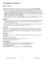
Страница 12: ...ion switch ON OFF will reset the countdown Always at the end of the countdown the PDU Timer will be in STANDBY mode B The ignition switch ON will always reset the countdown and prevent it from timing down override countdown mode and keep the PDU Timer ON Override The override circuit can be triggered by the PB push button momentary on switch on the PDU Timer Triggering the override will send the u...

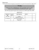
Страница 13: ... There are no user maintained parts Do not attempt to open or repair Contact your local distributor or D R Electronics for repair The following replacement parts and accessories are available for the PDU 42WB PARTS LIST PART NUM BER QUAN TITY DESCRIPTION NOTES PDU42WB 1 POWER DISTRIBUTION UNIT 212 0024WB 1 PDU 42WB OPERATION IN STALLATION MANUAL ...

Страница 14: ...U ignition ter minal Incorrect connection to vehicle wiring harness Faulty Unit Verify ignition input connection Consult the factory specifications and wiring diagrams for the vehicle Verify that the ignition wire re ceives 12V when vehicle ignition is set to ON and vehicle is run ning Return unit for repair Timed outputs not on while ignition is ON Timing cycle incorrect Timing cycle does not end...

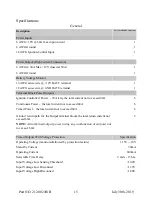
Страница 15: ...A relay the total current not to exceed 40A 6 Continuous Power the total current not to exceed 60A 6 Timed Power the total current not to exceed 60A 6 Ground return path for the Output terminal blocks the total return current not exceed 60A 5 NOTE All combined output power using any combination of outputs not to exceed 60A Timed Outputs With Voltage Protection Specification Operating Voltage monit...

Страница 16: ...es for removal or installation Lamps flash tubes batteries or other items considered consumables are not covered under warranty This warranty is in lieu of all other express warranties D R Electronics makes no warranties ex pressed or implied other than the express warranties contained herein WARRANTY PRODUCT RETURN POLICY In order to provide you with faster service product returns for repair or r...

Отзывы: