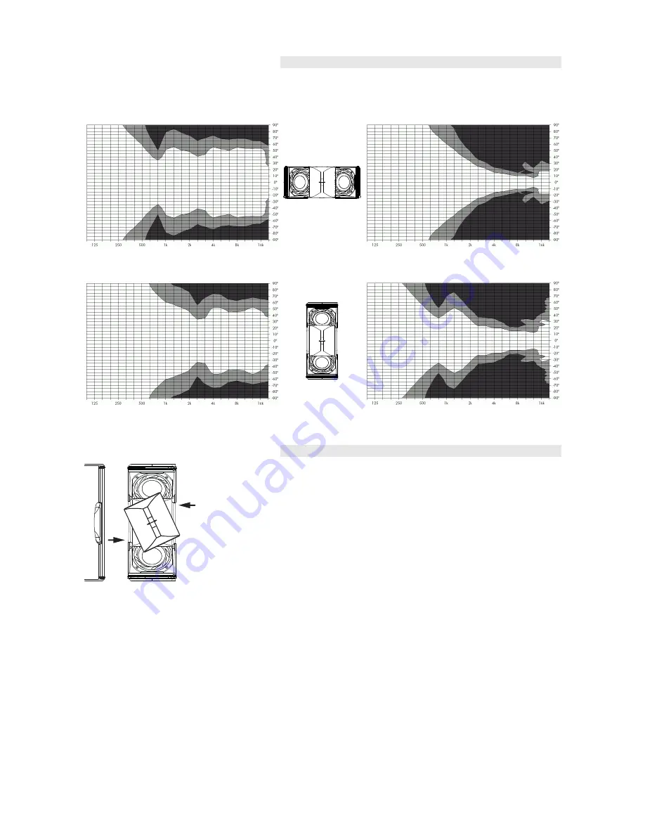
Dispersion characteristics
The graphs below show dispersion angle over frequency of a single T10
cabinet plotted using lines of equal sound pressure (isobars) at – 6 dB
and –12 dB.
Fig. 8: Isobar diagram T10 line source,
horizontal
Fig. 9: Isobar diagram T10 line source, vertical
Fig. 10: Isobar diagram T10 point source,
horizontal
Fig. 11: Isobar diagram T10 point source,
vertical
Altering the HF dispersion
Fig. 12: Rotating the horn
(shown without front grill for better illustration)
Swapping between point and line source setups is performed by simply
rotating the horn by 90°. The horn is easily accessible from outside of
the cabinet and can be rotated without any tools or removal of the
front grill.
This is achieved through apertures on the cabinet sides by a mechanism
that provides detents at both the line and point source positions.
T10 Manual
(1.0 EN)
Page 7 of 10
Содержание T10
Страница 1: ...T10 Manual 1 0 EN...


