17
Electric Shift Sytem
Servicing Other Electric System Components
Installation of Improved Motor Housing
Cover (Production units effective Decem-
ber 1989)
The new cover (PN 113786) has a continuous sealing lip
around the outside edge which improves sealing against road
environment contamination. Previous cover is no longer avail-
able. Units currently in the field must be modified whenever a
new cover is installed.
Modification: Because the new cover encloses the entire rim
of the units cast nose piece, the base of the motor mounting
flange must be relieved slightly to prevent interference.
Note: This modification is only needed if a notch is NOT
present in the motor housing flange.
1. Remove four (4) cover screws. Retain 3 screws.
Note: The service kit includes a screw which is 1/4" longer
than the previous cover screws.
2. Place the new cover into position on the shift unit
housing and draw a reference line on the motor base
to show the width of the area to be modified.
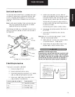
3. Using a file or small die grinder, remove material
from the motor base (as shown in Fig. 1. The notch
should be at least 0.100" (2.5mm) deep and 0.150"
(3.8 mm) wide. Trial fit the cover during modifica-
tion.
CAUTION: When removing material, use care to avoid filing
into the threads of the motor mount fastener.
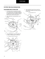
Fig. 1 - Electric Shift Unit Cover Fit Modifications
4. With the modification complete, install the new cover
as follows:
5. Using RTV gasket compound (supplied with the ser-
vice kit), apply a thin bead on top edge of motor
housing.
Note: The new cover does not require a gasket.
CAUTION: Always use RTV Electrical Grade Gasket Com-
pound (PN 113771). Standard forms of RTV generate
acetic acid which will damage shift unit components. Use
gasket compound sparingly. Excessive use of compound
could damage internal parts.
CAUTION
Cover
See Detail Below
Interference Area
Upper
Housing
Motor
Upper
Housing
0.100"
2.5 mm
Motor
0.150"
4.0 mm
CAUTION


