13
i Po r t I W- 2 0 / I W- 2 1 / I W- 2 2
I n s t r u c t i o n M a nu a l
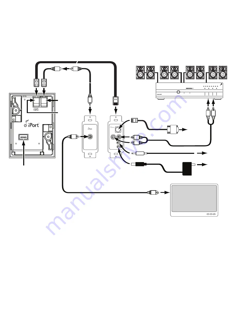
3. Plug the audio Cat5 cable into the A
UDIO
connection on the iPort and the RJ45 connector on the rear of the audio/IR wall
plate, as shown in
Figure 10
.
4. Plug the RJ45 end of the unbalanced video cable into the V
IDEO
connection on the iPort. Plug the female RCA end of the
unbalanced video cable into the male RCA cable you ran through the wall to the wall plate. Plug the other end of the male
RCA cable into the RCA jack on the rear of the unbalanced video wall plate. See
Figure 10
.
To Video
Wall Plate
Supplemental Power
GND
+15V
GND
+15V
VIDEO
RS 232
AUDIO
IR
PWR
C
AT
5/RJ-45 C
ABLE
(
UP
TO
500
FEET
—
NOT
INCLUDED
)
RJ-45
Video
Connector
RJ-45
Audio
Connector
To RJ-45
Connector on
Wall Plate
Rear
To A
UDIO
Connectors
To RS-232
Connector
To V
IDEO
Connector
To
Composite
Video Input
To PWR Connector
S
TEREO
RCA C
ABLE
(
NOT
INCLUDED
)
C
OMPOSITE
V
IDEO
C
ABLE
(
NOT
INCLUDED
)
To
Wall Outlet
To
Control System
IR Output
To
Control System
RS-232 Output
iPort (rear)
iPort
Balanced
Audio
Wall Plate
iPort
Unbalanced
Video
Wall Plate
Power
Supply
Audio System
Local-Zone Video System
3.5
MM
C
ABLE
(
NOT
INCLUDED
)
RS-232 C
ABLE
(
INCLUDED
)
To IR Connector
To RCA
Connector on
Wall Plate
Rear
U
NBALANCED
V
IDEO
C
ABLE
(
INCLUDED
)
M
ALE
-
TO
-M
ALE
RCA C
ABLE
(
UP
TO
30
FEET
,
NOT
INCLUDED
)
Supplemental
Power Connector
(see
Step 6
,
on page 14)
A.C. ON
AUTO ON
LR
LR
LR
LR
1 – 2
3 – 4
5 – 6
7 – 8
PROTECTION
BBE ON
ACTIVE
ACTIVE
POWER
Figure 10: iPort IW-22 System Connections
All manuals and user guides at all-guides.com


