


DS3112
49 of 133
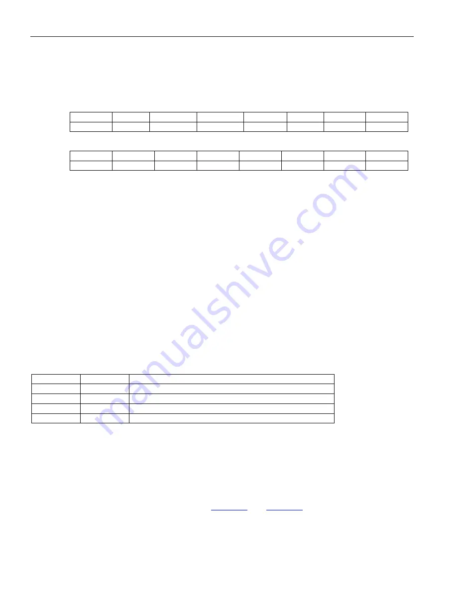
5.4 T3/E3 Framer Control Register Description
Register Name:
T3E3CR
Register Description:
T3/E3 Control Register
Register Address:
10h
Bit
# 7
6 5 4 3
2
1 0
Name DLB
LLB
T3IDLE
E3SnC1
E3SnC0
TPT
TRAI
TAIS
Default 0 0 0
0
0 0 0 0
Bit
# 15 14 13 12 11 10 9 8
Name —
PLB
TFEBE
AFEBED
ECC
FECC1
FECC0
E3CVE
Default
— 0 0 0 0 0 0 0
Bit 0: T3/E3 Transmit Alarm Indication Signal (TAIS).
When this bit is set high in the T3 mode, the transmitter
will generate a properly F-bit and M-bit framed 101010... data pattern with both X bits set to one, all C bits set to
zero, and the proper P bits. This is true regardless of whether the device is in the C-Bit Parity mode or not. When
this bit is set high in the E3 mode, the transmitter will generate an unframed all ones. When this bit it set low,
normal data is transmitted.
0 = do not transmit AIS
1 = transmit AIS
Bit 1: T3/E3 Transmit Remote Alarm Indication (TRAI).
When this bit is set high in the T3 mode, both X bits
will be set to a zero. When this bit is set high in the E3 mode, the RAI bit (bit number 11 of each E3 frame) will be
set to a one. When this bit it set low in the T3 mode, both X bits will be set to one. When this bit is set low in the
E3 mode, the RAI bit will be set to a zero.
0 = do not transmit RAI
1 = transmit RAI
Bit 2: T3/E3 Transmit Pass Through Enable (TPT).
0 = enable the framer to insert framing and overhead bits
1 = framer will not insert any framing or overhead bits
Bits 3 and 4: E3 National Bit Control Bits 0 and 1 (E3SnC0 and E3SnC1).
These bits determine from where the
E3 national bit is sourced. On the receive side, the Sn bit is always routed to the T3E3INFO Register as well as the
HDLC controller and the FEAC controller. These bits are ignored in the T3 mode.
E3SnC1
E3SnC0
SOURCE OF THE E3 NATIONAL BIT (Sn)
0
0
Force the Sn bit to one
0
1
Use the HDLC controller to source the Sn bit
1
0
Use the FEAC controller to source the Sn bit
1
1
Force the Sn bit to zero
Bit 5: Transmit T3 Idle Signal Enable (T3IDLE).
When this bit is set high, the T3 Idle Signal will be transmitted
instead of the normal transmit data. The T3 Idle Signal is defined as a normally T3 framed pattern (i.e., with the
proper F bits and M bits along with the proper P bits) where the information bit fields are completely filled with a
data pattern of ...1100... and the C bits in Subframe 3 are set to zero and both X bits are set to one. This bit is
ignored in the E3 mode.
0 = transmit data normally
1 = transmit T3 Idle Signal
Bit 6: T3/E3 Line Loopback Enable (LLB).
See
for a visual description of this
loopback.
0 = disable loopback
1 = enable loopback