The unit with a selected control system is rated for connection to three-phase ac 400 V / 50 Hz power
mains. Connection to power mains of the unit with any control system must be performed with
insulated, durable and heat-resistant conductors (cables, wires).
The external power input 400 V / 50 Hz must be equipped with an automatic circuit breaker built into
the stationary wiring to disconnect all the power mains phases. The circuit breaker QF position must
ensure free access for quick power-off of the unit. The circuit breaker trip current must be in
compliance with the current consumption of a specific E-HP model.
The recommended circuit breaker trip current and the cable cross sections for various Е-HP models
are given un the table below. However, the conductor selection shall be based on the maximum
permissible wire heating depending on the wire type, its insulation, length and installation method
(i.e. overhead, in channels or inside the walls)
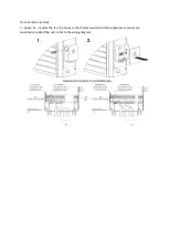
Terminal block x1 (in the control circuit):
RT1 – temperature sensor;
TK1 – self-resettable thermal switch (normally closed contact), response tempe50 °C;
TK2 – manually resettable thermal switch (normally closed contact), response tempe90 °C;
Connect the thermal switch contacts in series to the circuit of the starter (contactor) actuating coil
that starts the unit or the heater. In case of overheating one of the contacts gets broken and
switches the starter actuating coil off to cut power off and stop the motor.
Terminal block x2 (heaters):
L1, L2, L3 – phases (for Е-HP 9,12,15);
1L1, 1L2, 1L3, 2L1, 2L2, 2L3 – phases (for Е-HP 18,24,30);
N – neutral;
PE – protecting grounding.
Unit name
Rated circuit breaker trip current [A]
Number of conductors and cross section [mm
2
]
Е-HP -9
20
5х2,5
Е-HP-12
25
5х2,5
Е-HP -15
31,5
5х4,0
Е-HP -18
40
5х6,0
Е-HP -24
50
5х10,0
Е-HP -30
63
5х10,0

