PPX-1050 Series Panel Installation & Service Quick Guide
Page 2 of 3
DD5004860
Rev 00
05 January 2022
201 Daktronics Drive
Brookings, SD 57006-5128
www.daktronics.com/support
800.325.8766
Panel-to-Panel Connection
1.
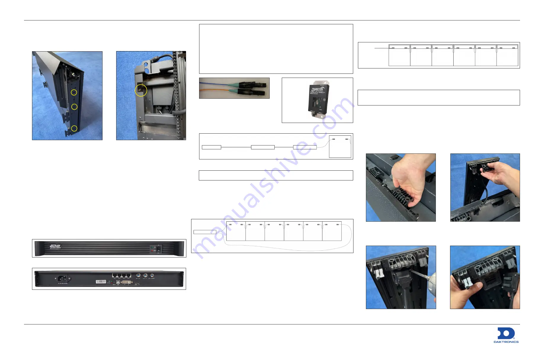
Place two panels side-by-side on the wall and secure the panels
together with M10 screws and nuts at three fixing points on the side of
each panel. Refer to
Figure 16:
Secure Panels Together
2.
Route power and signal cables
between panels directly from the top.
Electrical Installation
Signal Connection
A DVI cable connects a computer located in the control room to a
sending box. Some sending boxes may have additional signal input
options, such as HDMI and SDI. The sending box passes signal via a
Cat 5e/Cat 6 cable into the receiver card located inside the first panel.
Each panel has a receiver card, and Cat 5e/Cat 6 cables daisy-chain the
receiver cards together. The last panel can connect back to the sending
box for redundant data to the receiver cards if desired.
1.
Connect the sending box to the computer with a DVI cable. Refer to
.
Figure 18:
Sending Box (Front)
Figure 19:
Sending Box (Rear)
2.
Connect a Cat 5e/Cat 6 cable from the sending box RJ45 output jack
to the RJ45 quick-connect jack in the first panel. Refer to the
contract-specific Riser Diagram.
Figure 17:
M10 Fastener (Front View
with Module Removed)
Note:
The maximum cable distance from the sending box to the first receiver
card is 328.08' [100 m]. For installations exceeding this distance, use
a fiber converter to convert the Cat 5e/Cat 6 cable to a fiber cable,
which offers an additional 984.25' [300 m] with multi-mode fiber or up
to 9.32 mi [15 km] with single-mode fiber. Two fiber converters can be
used to convert the cable to a fiber cable and then back to a
Cat 5e/Cat 6 cable. The cable can connect to the first panel. Use
additional cables to connect to the next panel. Refer to
and
.
Figure 20:
Fiber Cable
3.
Route the Cat 5e/Cat 6 cable from
the signal output jack to the signal
input jack on the next panel. Refer
to
and the Riser Diagram.
Figure 22:
Route Cables
Sending box
Fiber converter
Fiber
Cat 5e/Cat 6
Fiber converter
Cat 5e/Cat 6
Note:
Routing may vary based on converter type.
4.
Connect the last panel back to the sending box for redundant signal
connection if desired.
5.
Refer to the
NovaStar
®
LED Display Control System M3 User’s Manual
for
details on how to configure the system and run the display.
Refer to
for an example of six panels connected together.
Sending box
Primary
Redundant (optional)
Figure 23:
Connect Signal
Power Connection
Most standard panels come with power quick connects with
pre-terminated connectors at each end.
The gender is different for the power input and output ends. Power
interconnect cables are shipped with the displays. Typically, every six
panels needs a new power input cable. Refer to the contract-specific Riser
Diagram for more details.
Figure 21:
Fiber Converter
The main power input cable has a pre-terminated connector at one
end and bare wires at the other end. Only horizontal interconnects are
.
To main
CIR #1
Figure 24:
Route Power Cables
Service
Note:
Avoid exposing the contents of the power/signal box to moisture,
as the components are not sealed for water exposure.
Module Removal
1.
Disconnect power to the display.
2.
Unlock the top locks and slide the cover back to remove the top cover.
Refer to
.
3.
Use the handle at the top of the module to slide the module up and
out of the panel. Refer to
Figure 25:
Slide Module Up
4.
Use a screwdriver to remove the four screws connecting the module
cable and then disconnect the cable. Refer to
.
Figure 27:
Remove Module Cable
Screws
Figure 28:
Disconnect Module
Cable
Figure 26:
Slide Module Out


