Daktronics 5000 Series Скачать руководство пользователя страница 27

Test and Replace the Multi-Direction Light Sensor

23

8  Test and Replace the Multi-Direction Light Sensor

Troubleshoot Multi-Direction Light Sensor (MDLS) Issues

The table below lists the crucial items to check if there are issues with the MDLS.

Item

Image

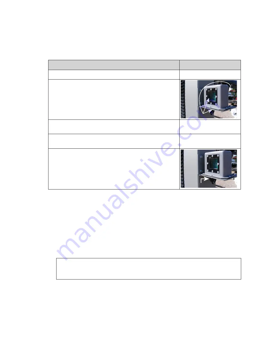
If there is a splice cable attached, inspect the connection.

Inspect the MDLS windows for cleanliness.

Check the connections at the back of the display to make sure 

they are secure.

Inspect the cable from the back of the display to the MDLS for 

damage. If needed, order a replacement cable.

Inspect the cable going into the bottom of the MDLS to see if it 

was pulled loose.

Test the MDLS

To test a MDLS, cover it with a piece of heavy cloth. The display should dim within a 

couple of minutes. Remove the fabric and verify the display returns to the brighter 

setting. If possible, work with the help desk and have them monitor the display IDM 

dimming levels.

Replace the MDLS

Required Tools: Pliers, side cutters

1� 

Disconnect the MDLS from the quick connect on the back of the display.

Note: 

There may be a splice in the cable between the MDLS and the display back. 

If so, disconnect the MDLS cable at the splice point, not at the back of the 

display.

2� 

Remove the cable that runs from the quick connect to the MDLS.

3� 

Remove the two attachment bolts that secure the MDLS assembly to the mounting 

arm.

4� 

Reverse Steps 1 - 3 to reinstall a MDLS.

5� 

Using cable ties, secure the MDLS cable to along the back of the display.

6� 

Work with the help desk to test the photocell and ensure it is functioning properly.

Windows (x3)

MDLS Cable

Содержание 5000 Series

Страница 1: ...201 Daktronics Drive Brookings SD 57006 5128 www daktronics com support 800 325 8766 5000 SERIES DIGITAL BILLBOARD SERVICE MANUAL P1810 DD3222902 Rev 01 17 July 2018 ...

Страница 2: ...part of this book covered by the copyrights hereon may be reproduced or copied in any form or by any means graphic electronic or mechanical including photocopying taping or information storage and retrieval systems without written permission of the publisher Daktronics trademarks are property of Daktronics Inc All other trademarks are property of their respective companies ...

Страница 3: ...ink For Module Access 15 6 Test and Replace Display Components 16 Test a Module 16 Module Status Indicators 16 Perform a Module Self Test 16 Replace Module Power Supplies 16 Replace a Module Power Supply 16 Test and Replace a ProLink Router 17 Test a PLR 17 Replace a ProLink Router 18 Replace PLR Power Supplies 18 Replace a Display Fan 18 7 Control Equipment Overview Service and Replacement 19 Con...

Страница 4: ...This page intentionally left blank ...

Страница 5: ... might interfere with local communication channels from the power system Module Consists of a display board with LEDs a driver board or logic card housing a module latch assembly and a louver Each module is individually removable from either the front or back of the display Module part numbers vary by pixel pitch ProLink Router PLR The PLR takes data in and then routes that data to other areas in ...

Страница 6: ...g in the spare parts rack for a list of the parts Contact the Account Service Manager ASM to order additional spare parts Description Daktronics Part Number Module Varies by pixel pitch PLR 6050 W Hook Mount 0A 1487 6009 28 SATA Cable W 2410 Power Supply A 2476 LC LC Duplex Fiber Cable W 1767 30 4 Pin Male to 4 Pin Female Cable W 1820 3 3 Pin Male to 3 Pin Female Cable W 2510 Filters Modules Power...

Страница 7: ...d replacement screws in a bag in the spare parts area Remove Module From Spare Parts Rack 1 With one hand on the module face insert the 1 8 hex head wrench into the bottom access hole 2 Turn the latch release approximately a quarter turn counterclockwise 3 Insert the 1 8 hex head wrench into the top access hole 4 Turn the latch release approximately a quarter turn counterclockwise You should feel ...

Страница 8: ...aki Router A 3665 Surge Suppressor A 3677 DMP 8065 2 0A 1603 8200 Power Supply A 2476 Light Sensor 0A 1604 4620 3 Pole Contactor A 3157 Ethernet Switch A 1815 Axial Fan 4 A B 1045 500 W Heater A 1819 Axial Fan 17 A B 1094 POE Injector A 3126 12 VDC Relay K 1040 Mobotix Webcam A 3127 28 SATA Cable W 2885 SmartLinkTM A 3707 72 SATA Cable W2889 Temperature Sensor 0A 1151 0013 Line Filter Z 1002 60 V ...

Страница 9: ...on Power to the display section enters into the termination panel and is redistributed to the power supplies Refer to the layout drawing for display specific power distribution Display Signal Overview This section provides generic signal path illustrations for even tall sections Figure 10 and odd tall sections Figure 11 Signal is sent from the DMP 8065 and is sent to the ProLink Router PLR in the ...

Страница 10: ...B 2 B 2 B 3 B 3 B 4 B 3 B 3 B 3 C 1 B 3 C 1 C 1 C 1 C 2 C 2 C 2 C 2 C 3 C 3 C 4 C 3 C 3 C 3 C 3 D 1 D 1 D 1 D 1 D 2 D 2 D 2 D 2 D 3 D 3 D 4 D 3 D 3 D 3 D 3 E 1 E 1 E 3 E 1 E 1 E 3 E 2 E 2 E 3 E 2 E 2 E 3 E 3 E 3 E 4 F 3 F 3 F 4 F 2 F 2 F 3 F 2 F 2 F 3 F 1 F 1 F 3 F 1 F 1 F 3 1 18 19 52 53 54 55 56 57 58 59 60 61 62 63 64 65 66 67 68 69 70 71 72 73 74 75 76 77 78 79 80 81 82 83 84 85 86 87 36 35 90...

Страница 11: ...1 Verify there is power to site by ensuring the power supply indicators are on If they are on there is power to site and it is most likely a signal issue If there is site power continue to Step 3 2 Verify the contactors for each display section are closed and allowing power to the display and control system 3 Verify the ProLink Router PLR is receiving power If the LED indicator lights are on unplu...

Страница 12: ...ser If this issue appears when there is white or light content it is possible there is insufficient power to the display If this is the case work with an electrician to establish the correct site power 5 Verify the PLR has power and is functioning Disconnect and reconnect power to the PLR 6 Verify there is power to that display section by checking module status indicators on multiple modules If th...

Страница 13: ... power or signal it is most likely a module issue 2 Measure the site power to verify it meets Daktronics requirements If this issue is only seen with white or light colored content there is most likely a power issue If there is insufficient power work with an electrician to establish proper site power Display too bright 1 Immediately call Daktronics help desk and have them blank the display 2 Veri...

Страница 14: ... lanyard connected to the door Note After performing service or completing connections replace the display door and ensure it is attached to the safety lanyard and secured with a screw 10 24 X0 625 hex head Daktronics part number HC 1554 in the provided location on the top right side of each door Refer to Figure 13 Find replacement screws in a bag in the spare parts area Front Access Front access ...

Страница 15: ...rn the latch release approximately a quarter turn counterclockwise You should feel the module release from the display face 5 Pull the module from the display face just far enough to reach the back of the module 6 Disconnect the power and SATA cables from the back of the module 7 Gently place the module on a clean and dry surface Note If there is no place to set the module use a safety lanyard to ...

Страница 16: ...lowing steps 1 Attach one end of the safety lanyard to a lanyard ring on the top of the module 2 Feed the lanyard through the lanyard ring on the top of the display directly below the module that will be removed 3 Attach the other end of the lanyard to the lanyard attachment ring on the bottom of the module that will be removed Refer to Figure 16 4 Disconnect the SATA and power cables from the bac...

Страница 17: ...tch gear 7 Turn a quarter turn clockwise to disengage the module from the face sheet 8 Remove the module by pushing it away from the display face pivoting and rotating it 90 degrees and pulling it through the face sheet Note Ensure louver blades run lengthwise when pulling module through display face so they are not damaged by the face sheet 9 Repair or replace the module as needed 10 Reverse Step...

Страница 18: ... bottom latch gear approximately a quarter turn counterclockwise to engage the latch 7 Use the top module lanyard rings or the lanyard to pull the module firmly against the face sheet 8 With a 1 8 hex head wrench turn the top latch gear approximately a quarter turn counterclockwise to engage the latch 9 Connect the SATA and power cables to the back of the module Hinge and Remove the ISP Enclosure ...

Страница 19: ... it off the hinges 1 Locate the quarter turn latch at the top of the DMP 8065 2 Use a flathead screwdriver turn the quarter turn latch counter clockwise until the DMP 8065 disengages 3 Pull the DMP 8065 from the right to hinge it out of the way Refer to Figure 24 4 If needed carefully lift the DMP 8065 off of the hinges and set aside while ensuring power and signal cables do not get pinched Figure...

Страница 20: ...y for 10 seconds 3 Reconnect the power to start the self test 4 Verify the module is running a self test Remove the SATA cable and cycle power to the module to stop the self test Replace Module Power Supplies The power supply provides power from the term panel to the module For the 5000 series of digital billboards the module power supply is located on the uprights Each power supply typically cont...

Страница 21: ...s they all work and that visually the display is fine but there could still be a signal failure that will not show up visually because of redundancy The Amber Yellow and Magenta test patterns provide a way to find the normally non visual breaks After it shows the White test pattern the PLR shows a Yellow pattern but it only sends the that pattern out on port A no redundancy any modules that receiv...

Страница 22: ...bly set screw 4 Lift the PLR assembly to disengage it from the display 5 Reverse Steps 2 4 to install the new PLR 6 Verify the cables are properly seated Replace PLR Power Supplies Each PLR has a power supply 1 Disconnect any power cables to the power supply and from that power supply to the PLR 2 Pull the power supply tab Refer to Figure 27 3 Rotate the power supply forward and lift it off of the...

Страница 23: ...iguration Open the ISP Enclosure To access ISP box components complete the following steps 1 Access the ISP enclosure by opening the rear access door with the control equipment label 2 Using a flathead screwdriver turn the two three quarter turn latches counterclockwise Refer to Figure 34 3 For easier access to ISP components the ISP enclosure door can be lifted off the hinges Connect a Laptop Som...

Страница 24: ...r or disposal Replace DMP Power Supplies Each DMP has a power supply To replace a failed DMP 8065 power supply 1 Disconnect any power cables to the power supply and from that power supply to the DMP 8065 2 Pull the power supply tab Refer to Figure 27 3 Rotate the power supply forward and lift it off of the pegs 4 Reverse Steps 1 3 to install a replacement power supply Replace the ISP Enclosure Fil...

Страница 25: ...n the SmartLinkTM to turn off This may take up to 8 minutes 3 Disconnect the incoming power wires in the SmartLinkTM 4 Disconnect the outgoing power wires from the relays R1 R2 R3 R4 5 Disconnect the RS232 cable and remove any cable ties securing it within the SmartLinkTM 6 Remove the four screws that secure the SmartLinkTM to the mounting plate 7 Reverse Steps 1 6 to install the new SmartLinkTM 8...

Страница 26: ... remove the four heater mounting bolts that secure the heater to the mounting plate 5 Reverse Steps 1 4 to install the new heater Replace the Fan Required Tools Phillips screwdriver 1 Disconnect the power wire to the fan 2 Using a Phillips screwdriver remove the four fan mounting bolts that secure the fan to the ISP enclosure Refer to Figure 39 3 Reverse Steps 1 2 to install the new fan Mounting P...

Страница 27: ...avy cloth The display should dim within a couple of minutes Remove the fabric and verify the display returns to the brighter setting If possible work with the help desk and have them monitor the display IDM dimming levels Replace the MDLS Required Tools Pliers side cutters 1 Disconnect the MDLS from the quick connect on the back of the display Note There may be a splice in the cable between the MD...

Страница 28: ...ort bolts 5 Work with Daktronics help desk to verify the webcam is focused and functioning properly Webcam Troubleshooting Perform the following basic power troubleshooting steps if the webcam is not functioning properly Refer to Figure 41 while reading the table below Issue Troubleshooting Steps Both LED indicators on the webcam are off 1 Check the Cat5 connections inside the surge protector to e...

Страница 29: ...SP box is connected and the LED indicators are on 2 If the LED indicators on the POE switch are on check the Ethernet connections from the Router to the POE switch from the POE switch to the back of the display and from the back of the display to the webcam The Ethernet cable may be damaged or disconnected 3 The POE surge may be damaged Use a RJ45 coupler to bypass 4 Request a new webcam ...

Страница 30: ...should be free of any errors prior to leaving the site Annual Inspection It is important to schedule annual maintenance visits on a digital billboard During the visit Replace ISP enclosure filters Inspect for loose modules Inspect the display for excess dust or debris Use the Digital Billboard Maintenance Checklist DD3059470 to record inspection findings Note After performing service or completing...

Страница 31: ...ntains drawings and quick guides that are generic to Daktronics digital billboards Project specific drawings and documents take precedence over the document in this section Performing a Daktronics Module Self Test DD1944805 ProLink Router 6050 Manual DD1735784 ...

Страница 32: ...This page intentionally left blank ...

Страница 33: ...Daktronics Warranty and Limitation of Liability 29 B Daktronics Warranty and Limitation of Liability Click here to view Warranty and Limitation of Liability SL 02374 information ...

Страница 34: ...This page intentionally left blank ...

Отзывы: