ZX-1
Ultrasonic Thickness Gauge
5
G. Small 14 Segment:
The material velocity, speed the sound wave travels
through a given medium/material, is displayed in this area, informing the user
what material the
ZX-1
is currently calibrated too. This area is also used for
alpha messages in the menu and edit modes.
H. Units:
This combination of icons are illuminated in different sequences to
inform the user what measurement units are currently being displayed in the
small 7 segment area.
I. Units:
This combination of icons are illuminated in different sequences to
inform the user what measurement units are currently being displayed in the
large 7 segment area.
J. Small 14 Segment:
The material type is displayed in this area. If it is set to a
value of one of the materials in our material list, it will be displayed in alpha
characters indicating the material type. Otherwise it will be set to CUST,
indicating custom material type.
K. Features:
The
ZX-1
can be locked once calibrated, to avoid accidently
changing the calibration. When this icon is illuminated, the
ZX-1
is in lock
mode. Refer to page 17 for an explanation on locking the
ZX-1
.
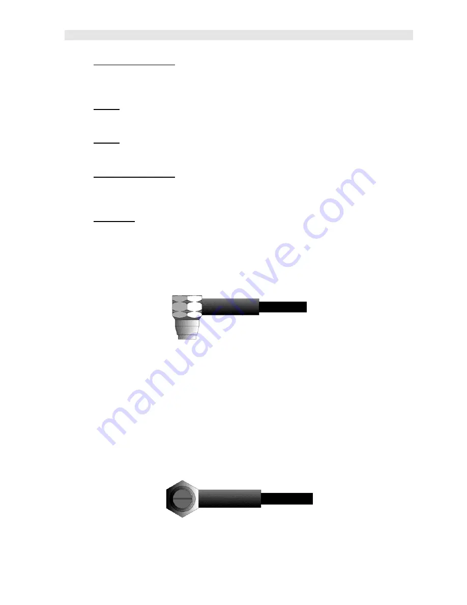
2.8 The Transducer
The Transducer is the “business end” of the
ZX-1
. It transmits and receives
ultrasonic sound waves that the
ZX-1
uses to calculate the thickness of the material
being measured. The transducer connects to the
ZX-1
via the attached cable, and
two coaxial connectors. When using transducers manufactured by Dakota
Ultrasonics, the orientation of the dual coaxial connectors is not critical: either plug
may be fitted to either socket in the
ZX-1
.
The transducer must be used correctly in order for the
ZX-1
to produce accurate,
reliable measurements. Below is a short description of the transducer, followed by
instructions for its use.


