background image


H9Q/H9QD User Manual


Author: CNR                              Revised by: MES                              Rev: 05/05/21                              Page 4 of 12 


V.


INSTALLATION


A.


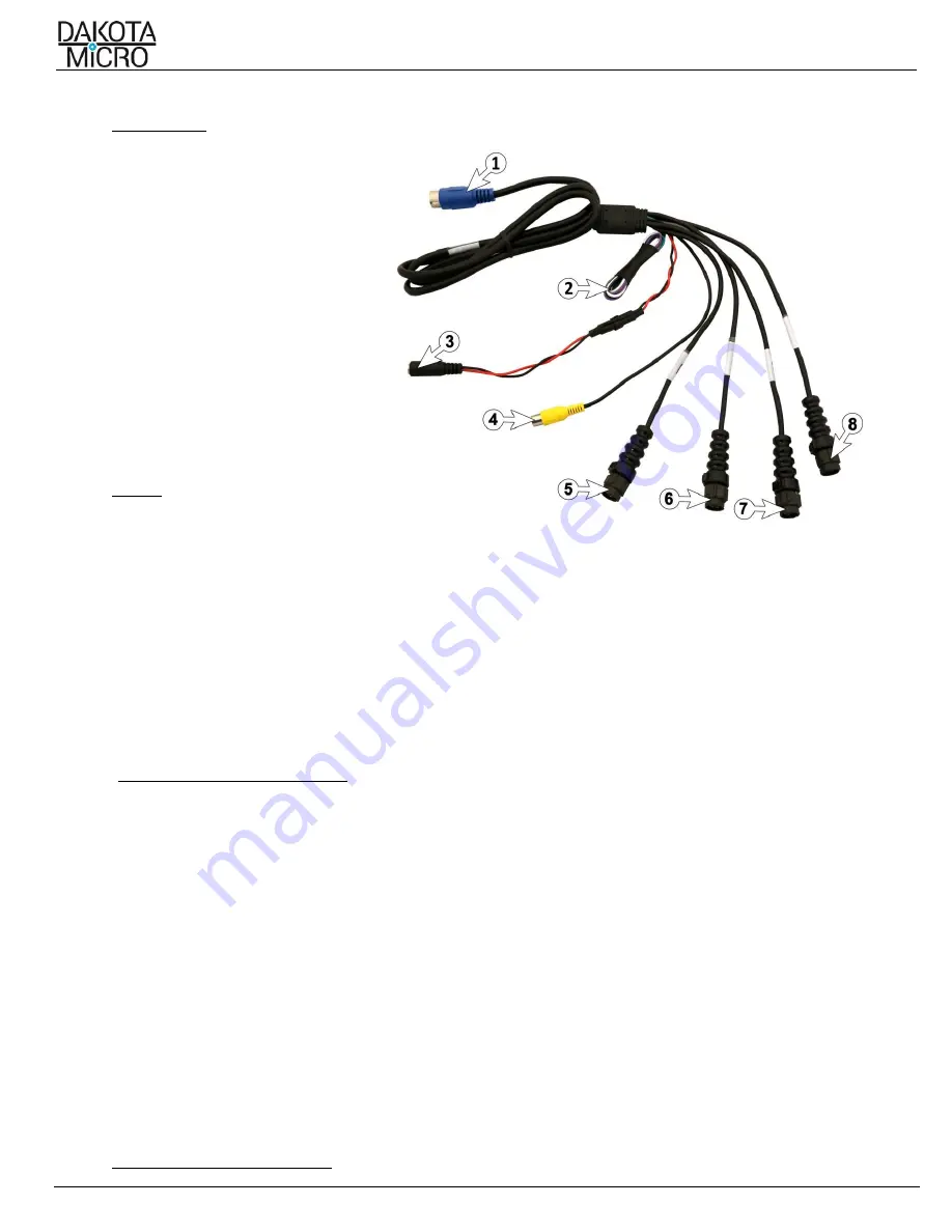
Monitor Wire Harness Details 
1.


Input to Monitor


2.


AV1-4 Event Trigger Wires


3.


Power Input


4.


RCA-Video Output


5.


AV1 

 Audio/Video Input


6.


AV2 

 Audio/Video Input


7.


AV3 

 Audio/Video Input


8.


AV4 

 Video Input


VI.


POWER 
 

A.


Supplying Power with 12v Power Adaptor


1.


Attach the power input connector (3 above) to your included 12v cigarette lighter power adaptor. 

2.


Plug cigarette lighter adaptor into 12v power source. 

B.    Hardwire Power Adaptor 

1.

     If you would like to hardwire your power supply, please contact your local AgCam® dealer for available hardwire 

power adaptors (PN: 

DM-HDWRE is included in four-camera kits only)


2.

    Dakota Micro hardwire power adaptors have a maximum circuit capability of 5 amp. 

C.    Fuses 

1.

   There is a small in-line blade fuse located on the red and black power wire (3 above). When replacing this fuse, use 

a MAX 2amp glass fuse. 

2.

   There is a small glass fuse located on the inside tip of the 12v portion of the power adaptor (PN: DMAC-12v). 

When replacing this fuse, use a MAX 2amp glass fuse. 


VII.


EVENT TRIGGER WIRE OPERATIONS 
 

A.   Event Trigger Wire Color Guide 

1.


Camera 1 

 Green 

2.


Camera 2 

 Purple 

3.


Camera 3 

 Gray 

4.


Camera 4 

 White 

B.   Event Trigger Wires Explained 


Event trigger wires can be attached to any 12v positive event.  This will cause the monitor to change to that camera, 
regardless of the state of the monitor (i.e. ON/OFF or channel selection). The most recent event will be the primary 
display. So, if two (2) video channels (AV1 & AV2) are attached to an event output, the event that happens last will 
change the monitor to its respective camera view.  
 
The wires can be attached to any positive output 10.5v to 16.9v switch or supply to cause the monitor to 
automatically switch the unit to its respective channel camera. 

Example:

 If you were to attach the AV1 wire to a 

positive output from an unloading auger on a combine, the monitor would switch from channel 2, 3, or 4 to channel 1 
when the auger is extended. The event circuit should be neutral in its normal state and change to HIGH (+12v) when 
the event is active.  


VIII.


MONITOR & REMOTE OPERATION


Содержание AG-H9QD

Страница 1: ...ll safety signs and precautions See the Dakota Micro Inc website for installation training videos at www dakotamicro com Table of Contents I Included Monitor 2 II Standard Features 3 III Important Inf...

Страница 2: ...Description Picture Dakota Micro Inc 9 AHD Quad Monitor Monitor Wire Harness PN DM H9QMWH Monitor Remote PN DM H9QRMT styles vary by kit battery is included A C Power Wall Plug PN DM PA3 styles vary b...

Страница 3: ...STALLATION MOUNTING A Mounting Precautions Remove your monitor carefully from packaging and inspect all mounting hardware Mounting location is the most important part of the monitor installation as it...

Страница 4: ...the inside tip of the 12v portion of the power adaptor PN DMAC 12v When replacing this fuse use a MAX 2amp glass fuse VII EVENT TRIGGER WIRE OPERATIONS A Event Trigger Wire Color Guide 1 Camera 1 Gree...

Страница 5: ...tween Quad screen cam 1 cam 2 cam 3 cam 4 Duration each camera remains on screen is able to be changed in AUDIO menu Auto Sequence Time 5 Key To decrease parameter Up Down 6 Key To increase parameter...

Страница 6: ...gation Arrows Navigation Arrows Navigation Arrows N A N A Next File Skip Standard Remote POWER ON give it a few seconds OFF Switches between video channels Displays Menu Navigation Arrows Navigation A...

Страница 7: ...sts the contrast of the image COLOR Adjusts the color of the image SHARPNESS Adjusts the sharpness of the image ADVANCED CONTROL Accesses additional display controls VIDEO ADVANCED CONTROL NOISE REDUC...

Страница 8: ...camera mirror functions AHD1 4 GUIDE LINE Turns ON OFF individual camera guide line B DVR Menu Settings 1 Press the ENT key on the remote Use the U D L R button to Select the correct User and Enter t...

Страница 9: ...Default BitRate Adjust the rate of the recording How smooth the images appear Low Middle High PLAYBACK Playback Menu Chnl Select playback channel to search 1 2 3 4 All Start time Select start time ra...

Страница 10: ...meters We always request that customers keep in mind that our less expensive OverView product line is cheaper because it does not feature the reliability and durability of our AgCam and EnduraCam line...

Страница 11: ...ormation RA Number provided by Dakota Micro Technical Support Shipping and associated costs to ship product to DM factory to be borne by the customer unless otherwise specified 5 Customer should mail...

Страница 12: ...orce the rights under this limited warranty the purchaser should follow the steps set forth in the complete Dakota Micro Warranty Repair Policy listed on page 11 section XVI and provide proof of purch...

Отзывы: