


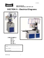


370 S 370 S L 370 PP 370 PP L
31
certain amount of jerking without the cylinder connected, this is normal. If the head jerks excessively future adjustments will be
needed.
Note
: If cylinder piston restricts your from moving the head the full length of the column, remove the bottom air line from the
cylinder, using compressed air, blow into the fitting and the piston will retract.
F
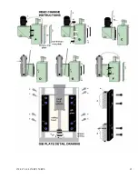
. If the gib blocks are too tight and can not be adjusted, it is recommended that the gib block faces be surface ground.
(Gib detail drawing ref d) After they are ground check fit, and adjust as needed or surface grind again, until gibs can be
adjusted.
G
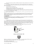
. Run the head feed cylinder piston through the head casting mounting hole a install the locking nut. (Figure E ref 6)
Tighten securely and replace the set screw in the lock nut and tighten.
H
. With the upper and lower tube lines removed form the cylinder and using compressed air run the head up and down
on the column. The head will now travel without jerky movements or hesitation. If these conditions still exist readjust the gib
blocks.
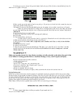
I. Replace the head limits cams into the “T” slots in the head. (Figure F ref 4)
J. Connect power back to the motor.
K. Replace rear column cover.
L. Reconnect any tube lines, wires, etc., that may have been removed before removing the head.
M. Reinstall Plexiglas hood in the correct position, and connect gas shocks, limit switch, etc. (If hood modifications
have not yet been made, do this modification now.)
Note: Once these adjustments and modifications have been made, and parts are replaced in original position, these
adjustments / modification will not be needed again.
Once these adjustments are made it should be a simple change.
1. Remove hood.
2. Disconnect electrical to motor and tubing etc.
3. Remove rear cover unbolt gib plates, and cylinder.
4. Remove head, put on replacement head.
5. Install gib plates, replace nut on cylinder piston.
6. put on rear cover, rewire, and connect all tubes.
7. Replace hood.
8. Start cutting!
Содержание Euromatic 370 PP
Страница 9: ...370 S 370 S L 370 PP 370 PP L 9 ...
Страница 10: ...370 S 370 S L 370 PP 370 PP L 10 Actual control panel layout may vari ...
Страница 32: ...370 S 370 S L 370 PP 370 PP L 32 ...
Страница 33: ...370 S 370 S L 370 PP 370 PP L 33 ...
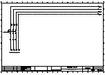
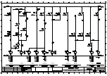
Страница 38: ...ALIMENTAZIONE 230V 60Hz 230V 60Hz POWER SUPPLY POWER SUPPLY ...
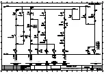
Страница 39: ...HL4 ILLUMINAZIONE LAMA POWER SUPPLY ...
Страница 40: ...LAMPEGGIATORE LAMA IN MOTO 24VAC MORSA 24VAC EMERGENCIES ...
Страница 41: ...DISCESA TESTA EV DISCESA TESTA START MEMORIA PULSANTE CICLO SB4 START CICLO ELECTROMECHANICALCIRCUIT ...
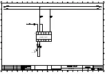
Страница 44: ...9 11 2 4 5 10 3 6 7 8 1 CH1 LC4HR424ACJ KA5 RITORNO CARRO COUNTER ...
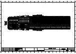
Страница 45: ...TERMINAL ...
Страница 49: ...10 2 2019 Euromatic 370 2 Head Cylinder Unit Ref 005 ...
Страница 51: ...10 2 2019 Euromatic 370 4 Bedplate Unit Ref 008 ...
Страница 53: ...10 2 2019 Euromatic 370 6 Head Unit Ref 002 ...
Страница 55: ...10 2 2019 Euromatic 370 8 Vise Unit Ref 004 ...
Страница 57: ...10 2 2019 Euromatic 370 10 Group Feeder P R ...
Страница 59: ...10 2 2019 Euromatic 370 12 Group Alimentador P P Ref 014b Alimentador Ref 014b ...