background image


Page  12  of 48


SK2019 EU FDHD-V/P-AC-001 

A.6.2.


Modulating Valve Models 


Model Definitions 

1.


3/4" inch 2-way modulating valve and 24VAC actuator with 0-10VDC input 

2.


3/4" inch 3-way modulating valve and 24VAC actuator with 0-10VDC input 

3.


1" inch 2-way modulating valve and 24VAC actuator with 0-10VDC input   

4.


1" inch 3-way modulating valve and 24VAC actuator with 0-10VDC input which is used with unit~S2/W2 


Specifications 

24VAC power supply   
0~10VDC control signal 
Bi-directional modulating proportional control 
Working media: cool/hot water or with 60% glycol 
Media Temp. Range: 34°F to 203°F (1°C to 95°C)   
Rating pressure: 2.0MPa 
Max. Differential Pressure: 0.3MPa 
Opening or closing time: 50 sec.(50Hz), 40 sec.(60Hz) 
Connection: NPT internal thread 
 

Dimensions 


Size 

Type 

Kv Value 

Dimension 

3/4

 (DN20)   

2-way 

4.6 

115 

73 

67 

89 

90 

3/4

 (DN20)     

3-way 

6.8 

127 

73 

67 

89 

90 

1

 (DN20)   

2-way 

4.6 

117 

73 

67 

93 

90 

1

 (DN20) 

3-way 

5.7 

139 

73 

67 

93 

90 

 
(All dimensions shown in mm) 


Содержание FDHD-100-P

Страница 1: ...D 36R V FDHD 48 V FDHD 60B V FDHD 75 V FDHD 100 V HIGH PRESSURE DUCT FDHD Serie FDHD V P AC MOTOR Edition R00 Models INSTALLATION AND MAINTENANCE MANUAL FDHD 18R P FDHD 24R P FDHD 30R P FDHD 36R P FDHD 48 P FDHD 60B P FDHD 75 P FDHD 100 P ...

Страница 2: ...stage in the manufacturing of our products Throughout the production process we maintain strict control starting with our extensive resources in research and development through to the design and manufacture of almost every individual component from molded plastics to the assembly of units and controllers EUROVENT CERTIFICATION Quality Controlled from Start to Finish Our highly trained staff and s...

Страница 3: ...nance 19 C 3 Filter Cleaning 19 C 4 Fan Motor Assembly Maintenance 19 D Control Specifications Complete Function PCB AC S1 20 D 1 I O Port Definitions 20 D 2 Wiring Diagram 21 D 2 1 Complete Function PCB AC S1 21 D 3 Configuration Settings 22 D 3 1 Fan Coil Unit ON OFF 23 D 3 2 Auto Restart 23 D 4 Control Logics for 2 Pipe System 24 D 4 1 With Valve Configuration 24 D 4 2 Without Valve Configurati...

Страница 4: ... Control Settings 33 D 15 2 Master Slave Network Setup 34 D 15 3 Master Slave Communication Method 36 D 16 Open Modbus Protocol 37 E User Interface 40 E 1 Remote Handset 40 E 2 Wired Wall Pad Controller 41 F Sensor Resistance R T Conversion Table 45 G Troubleshooting 46 H Accessories 47 ...

Страница 5: ...omplete function onboard PCB with integrated group control functionality T Terminal strip only P Chilled Hot Water 4 Pipe V Chilled Hot Water 2 Pipe 18 100 Unit Sizes See General Specification section A for cooling and heating capacities FDHD High Static Hydronic Ducted Fan Coil ...

Страница 6: ... internal thermal overload protection The unit is using 3 speed AC motor AIR FILTER The filter is easily removable and washable and is made from self extinguishing acrylic with a class EU2 G2 Merv 2 4 efficiency rating G4 or F8 Merv 8 14 efficiency filter is optional DRAIN PAN The drain pan fits a drain pipe of Ø 21mm on both left and right side of drain pan and is with fire resistant insulation C...

Страница 7: ...7 60 57 54 64 60 56 64 61 57 65 59 54 66 63 60 Sound Power Level Outlet e 65 62 60 64 62 58 67 64 61 72 70 67 73 69 63 69 67 64 71 68 65 75 72 69 Sound Power Level Inlet Radiated 65 62 60 64 62 59 67 64 61 72 70 67 73 68 66 72 70 67 74 71 68 75 72 69 Electrical Fan Motor Power H W 300 308 380 476 570 625 813 988 M 232 261 310 418 450 520 600 885 L 203 222 260 389 395 464 483 745 Fan Motor Running ...

Страница 8: ...8 11 93 14 36 15 43 16 73 9 97 20 86 Water Content Hot Water L 0 37 0 638 0 638 0 638 1 12 1 12 1 29 1 59 Heating mode 4 pipe Return air temperature 20C Inlet outlet water temperature 65C 55C Coil Data 2 Pipe System Model Fin height mm Fin Length mm Fins per Inch No of Rows Fin width mm No of Circuits Tube Ø mm FDHD 18R V 275 534 12 7 3 64 95 4 9 52 FDHD 24R V 275 934 12 7 3 64 95 6 FDHD 30R V 275...

Страница 9: ...28 3 27 3 25 3 24 1 19 8 16 9 28 8 25 7 20 4 35 4 31 6 29 9 16000 0 Hz 17 6 16 0 14 4 13 7 10 3 8 6 17 8 14 9 10 4 23 9 19 5 18 2 Model FDHD 48 FDHD 60B FDHD 75 FDHD 100 speed H M L H M L H M L H M L Sound Power dB A 68 6 63 4 61 2 69 8 66 7 64 7 67 2 61 0 56 7 69 3 66 9 63 6 Sound Power in 1 3 Octave bands under rated ESP dB 20 0 Hz 22 6 16 6 22 9 22 2 27 6 20 7 25 5 17 5 16 8 27 1 23 0 25 3 25 0...

Страница 10: ...475 630 60 φ14 300 FDHD 48 60 V 1460 1392 1430 495 650 60 φ14 380 FDHD 75 V 1460 1392 1430 595 750 70 φ14 430 FDHD 100 V 1760 1692 1730 595 750 70 φ14 430 Model I J K L X Y R Inch FDHD 18 V 240 30 40 50 65 150 3 4 FDHD 24 30 36 V 240 30 40 50 65 150 3 4 FDHD 48 60 V 320 30 40 50 65 225 3 4 FDHD 75 V 370 30 40 50 65 275 1 FDHD 100 V 370 30 40 50 65 275 1 All dimensions shown in mm ...

Страница 11: ...8 60 P 1460 1392 1430 495 650 60 φ14 380 320 FDHD 75 P 1460 1392 30 595 750 70 φ14 430 370 FDHD 100 P 1760 1692 1730 595 750 70 φ14 430 370 Model J K L X Y V W P R Inch FDHD 18 P 30 40 50 65 150 22 80 22 3 4 FDHD 24 30 36 P 30 40 50 65 150 22 80 22 3 4 FDHD 48 60 P 30 40 50 65 225 22 150 22 3 4 FDHD 75 P 30 40 50 65 275 22 200 22 1 FDHD 100 P 30 40 50 65 275 22 200 22 1 All dimensions shown in mm ...

Страница 12: ...zed actuator Specifications Medium Cool Hot water or 60 glycol Structure Two way or Three way Operating Mode On Off Power Supply AC220V Power Consumption 6W during valve position change Running Times 15 sec Pressure Rating 2MPa Media Temp Range 34 F to 203 F 1 C to 95 C Max Differential Pressure 1MPa Body Forged brass nickel plated Ball Chrome plated brass Stem Brass Seats Fiberglass reinforced Te...

Страница 13: ... which is used with unit S2 W2 Specifications 24VAC power supply 0 10VDC control signal Bi directional modulating proportional control Working media cool hot water or with 60 glycol Media Temp Range 34 F to 203 F 1 C to 95 C Rating pressure 2 0MPa Max Differential Pressure 0 3MPa Opening or closing time 50 sec 50Hz 40 sec 60Hz Connection NPT internal thread Dimensions Size Type Kv Value Dimension ...

Страница 14: ...servicing fan coil unit should be performed by qualified service personnel only This appliance is not intended for use by persons including children with reduced physical sensory or mental capabilities or persons lacking in experience and knowledge of the appliance unless they have been given supervision or instruction concerning it User of this appliance is responsible for his her own safety Warr...

Страница 15: ...pecification table for weight of the unit 4 The unit must be installed horizontally to ensure proper operation and condensate draining 5 The external static pressure of the ducting must be within the unit s static pressure range 6 Confirm that the unit has been switched OFF before installing or servicing the unit B 200mm 600mm _ CEILLING DRAIN PIPE Installation Procedures 1 The unit is designed to...

Страница 16: ...RUN CAUTION Make sure the top of the unit is level after installation The drain pan is designed with a slight gradient to facilitate drainage CAUTIONS Dimension M and N are determined by air duct design Air duct should be fire proof Please refer to concerned country national and local regulation Circulatory air pressure drop should be approximately equal to the External Static Pressure ...

Страница 17: ...ake sure the drain pipe has a slope of at least 2 cm m without obstructions or bottlenecks Fit a siphon if necessary which prevents air being sucked up by the drain hose Connect the condensate drain pipe to a rainwater drainage system Do not connect to the sewage system as odors may be sucked up if the water in the siphon evaporates Pour water into the pan and check if any leakage Air Purging Afte...

Страница 18: ...cordance with the relevant local and national legislation S Control Wiring Diagram Please refer to section D T1 Wiring Diagram for 230VAC Input Signal LOW HIGH MED M N RELAY RELAY RELAY Fan control FUSE Fuse EH element Protection switch L N Hi M Lo V1 V2 N Neutral Heating signal 230V Cooling valve signal 230V L speed signal 230V M speed signal 230V H speed signal 230V 1Ph 230V 50Hz Power input Ear...

Страница 19: ...d signal 24Vac H speed signal 24Vac Earth Yellow H Brown M Orange L 3 speed unit with EH Wiring scheme LOW HIGH MED M N RELAY RELAY RELAY Fan control FUSE COM Fuse EH element Protection switch Protection switch Fuse EH element Protection switch Fuse EH element Protection switch CONTROL LOAD LOAD LOAD L1 L2 L3 N 380 400V 3Ph 50 60Hz Neutral Live TR kit is optional IPA18 DL T24V 002 24Vac for thermo...

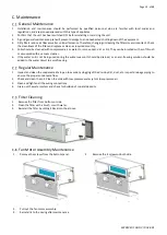
Страница 20: ...oft brush or vacuumed with a vacuum cleaner 6 If the water coil is not being used during the winter season it should be drained or an anti freezing solution should be added to the water circuit to avoid freezing Regular Maintenance 1 Inspect and clean the condensate drain pan to avoid any clogging of the drain by dirt dust etc Inspect drainage piping to ensure the proper condensate flow 2 Check an...

Страница 21: ...ted when Tr Ts 4ºC If Tr Ts cool operation will be terminated Heating operation will only be activated when Tr Ts 4ºC If Tr Ts heating operation will be terminated Float switch Float Voltage free NC The contact is closed before the float switch is turned on Electrical heater safety switch EH Voltage free NC The contact is closed before the EH is turned on Power input Phase L Power supply to the PC...

Страница 22: ... speed outpu AUX1 Voltage free contact ON unit in Heating mode AUX2 Voltage free contact ON unit in Cooling mode PRO Occupancy contact FLOAT Float swith for pump EH protectionl swith for elecctrical heater CN1 2 Stepping motor output TTL Wired wall pad AI3 Indoor coil temperature sensor 2 Ti2 AI2 Indoor coil temperature sensor 1 Ti1 AI1 Return air temperature sensor Tr X DIS1 LED recevier output R...

Страница 23: ...Page 22 of 48 SK2019 EU FDHD V P AC 001 Configuration Settings ...

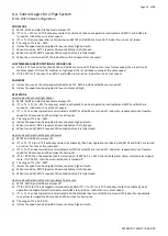
Страница 24: ...e of system failure or cessation of power supply The restored parameter data set depends on the type of user interface a Handset only user interface When the power ON signal is received by the fan coil unit and no wired wall pad is installed the Mode Fan Speed Set temperature will be the same as the handset setting before the last power OFF b Wall pad only OR wall pad and handset user interface Wh...

Страница 25: ...TV1 and AUX1 are turned off Indoor fan repeatedly runs at low fan speed for 30 seconds and then stops for 3 minutes d The range of Ts is 16 30ºC e Indoor fan speed can be adjusted to low medium high and auto f When turned on MTV1 requires 30 seconds before it is fully open g When turned off MTV1 requires 120 seconds before it is fully closed Heat mode with electrical heater as booster a MTV2 and A...

Страница 26: ...m DEHUMIDIFICATION MODE a MTV2 AUX1 and heater are always off b If Tr 25ºC then MTV1 and AUX2 will be ON for 3 minutes and then OFF for 4 minutes c If 16ºC Tr 25ºC then MTV1 and AUX2 will be ON for 3 minutes and then OFF for 6 minutes d If Tr 16ºC then MTV1 and AUX2 will be turned off for 4 minutes e At the end of the above dehumidification cycle the system will decide the next dehumidification co...

Страница 27: ...t operation is terminated and AUX1 is turned off Indoor fan repeatedly runs at low fan speed for 30 seconds and then stops for 3 minutes d The range of Ts is 16 30ºC e Indoor fan speed can be adjusted to low medium high and auto PRE HEAT Pre heat without electrical heater a MTV1 MTV2 and AUX2 are off b If Ti1 36 ºC or 28 ºC depending on DIP setting AUX1 is on while indoor fan remains off c If Ti1 ...

Страница 28: ...o low medium and high HEAT MODE Without Electrical Heater a MTV1 AUX2 and are heater always off b If Tr Ts 1ºC or 4ºC if economy contact is activated then heat operation is activated MTV2 and AUX1 are turned on Indoor fan runs at the set speed c If Tr Ts then heat operation is terminated MTV2 and AUX1 are turned off Indoor fan repeatedly runs at low fan speed for 30 seconds and then stops for 3 mi...

Страница 29: ...75ºC then MTV2 and AUX1 are turned off indoor fan remains on and runs at high speed b If Ti2 70ºC then MTV2 and AUX1 are turned on indoor fan remains on and runs at set speed c If the indoor coil temperature sensor is damaged then the protection mode will be overridden and the unit will work according to the pre heat and post heat set times DEHUMIDIFICATION MODE a MTV2 AUX1 and heater are always o...

Страница 30: ...peration will cancel the sleep mode The cool mode sleep profile is The heat mode sleep profile is Auto Fan Speed COOL MODE HEAT MODE Fan speed cannot change until it has run for more than 30 seconds Fan speed is regulated according to the profile below Fan speed cannot change until it has run for more than 30 seconds Fan speed is regulated according to the profile below Hour Sleep on 0 5 1 0 2 0 S...

Страница 31: ...he fan is not working the heater will be turned off immediately and report an error and fan speed will change to high speed Once the contact is returned to the closed position 60 seconds reset the error and the heater will start again When the EH safety switch is opened 3 times within 60 minutes the heater is not allowed to start anymore Turn off the unit to reset the fault provided that the switc...

Страница 32: ...aged 1 Check if Ti2 plug is connected or not 2 Check if sensor s resistance is correct or not Return air sensor failure Green LED blinks 3 times stops for 3s Room sensor unplugged or damaged 1 Check if Tr plug is connected or not 2 Check if sensor s resistance is correct or not Indoor coil sensor 1 failure Green LED blinks 4 times stops for 3s Ti1 sensor unplugged or damaged 1 Check if Ti1 plug is...

Страница 33: ... stops for 3s Check unit 15 communication plug and fix it Unit 16 failure RED LED blinks 16 times stops for 3s Check unit 16 communication plug and fix it Unit 17 failure RED LED blinks 17 times stops for 3s Check unit 17 communication plug and fix it Unit 18 failure RED LED blinks 18 times stops for 3s Check unit 18 communication plug and fix it Unit 19 failure RED LED blinks 19 times stops for 3...

Страница 34: ...Master Control Unit 1 Connect all the units PCBs according to the wire color and type of connector 2 Select the master unit by setting DIPA S1 SW6 to ON 1 in the PCB 3 Ensure the DIPA S1 SW6 is set to OFF 0 in the PCB on each slave unit 4 Switch on the units by connecting the main power supply 5 Using the handset set the operation parameters for the master unit which will automatically send the se...

Страница 35: ...box 2 Communication plug A B A B is printed on the main PCB When you connect the wires please ensure connection of A to A and B to B 3 Connection wire i If the total length of wire is more than 1000m please use shielded wire in order to protect the signal transmission ii Complete wire connection First unit Middle unit Last unit ...

Страница 36: ... wire contact by using a multimeter c Check 1 and 2 3 and 4 5 and 6 to be sure the connections are correct d If the resistance between two wire contacts is too high please check and reconnect the wire contacts 4 Reconnect the communication plug to the control box First unit Middle unit Last unit 1st contact 2nd contact 3rd contact 4th contact 5th contact 6th contact ...

Страница 37: ... 0 1 0 03 Slave 0 0 0 0 1 1 04 Slave 0 0 0 1 0 0 05 Slave 0 0 0 1 0 1 06 Slave 0 0 0 1 1 0 07 Slave 0 0 0 1 1 1 08 Slave 0 0 1 0 0 0 09 Slave 0 0 1 0 0 1 10 Slave 0 0 1 0 1 0 11 Slave 0 0 1 0 1 1 12 Slave 0 0 1 1 0 0 13 Slave 0 0 1 1 0 1 14 Slave 0 0 1 1 1 0 15 Slave 0 0 1 1 1 1 16 Slave 0 1 0 0 0 0 17 Slave 0 1 0 0 0 1 18 Slave 0 1 0 0 1 0 19 Slave 0 1 0 0 1 1 20 Slave 0 1 0 1 0 0 21 Slave 0 1 0 ...

Страница 38: ...e used to test unit Valid Error code table Error code Description Definition 01 01H Invalid commands Received commands beyond valid commands 02 02H Invalid data address Data addresses beyond valid data address 03 03H Invalid data Data beyond definition range 04 04H Write data not successful Write data did not succeed Coils table Description Address Type Remark Unit ON OFF 100000 R W Sleep mode 100...

Страница 39: ...W Calibration wired wall pad and set timer function Minute 300008 W Calibration wired wall pad and set timer function Second 300009 W Calibration wired wall pad and set timer function Hours in Timer on 300010 R W Timer ON Minute in Timer on 300011 R W Timer ON Hours in Timer off 300012 R W Timer OFF Minute in Timer off 300013 R W Timer OFF Icon of Timer ON or OFF 300014 R W BIT0 Icon of Timer ON B...

Страница 40: ...ed Bit7 Electrical heater failure Bit8 Motor1 Error Bit9 Motor2 Error Bit10 System parameters error Bit11 Anti frozen protection Bit12 Reserved Bit13 Reserved Bit14 Reserved Bit15 Reserved Fan speed status 400006 R Low 04 H Medium 02 H High 01 H Mode status 400007 R Cooling mode 01 H Dehumidify mode 02 H Fan mode 04 H Heating 08 H Setting temperature status 400008 R Testing only Room temperature i...

Страница 41: ...re automatically sent to the slave units Auto Cool Heat operation will be applicable in 4 pipe system only Swing and Louver functions are not applicable European version only uses degree C setting Swing It is not available Interchange o F and o C on Display Press up and down buttons for 3 seconds then release Louver It is not available ...

Страница 42: ... of 48 SK2019 EU FDHD V P AC 001 Wired Wall Pad Controller Day display Mode display Temperature display Fan speed display Timer display Real Time display Master Slave Button display Network Sleep icon Key lock ...

Страница 43: ...FF timer affects the local unit only The system supports ON OFF timer settings for each day of the week Press twice to enter Timer setting interface and timer icon is on When ON blinks press to set timer date from Monday to Sunday Press to set hour and minute of timer on or timer off alternately ON blinks when timer is set to on and OFF blinks when timer is set to off Press or to set timer on off ...

Страница 44: ...re unit setting Press and at the same time to change temperature unit between Celsius and Fahrenheit 11 Network control Only master unit can control slave units Press four times to set network control and NETWORK icon is on The slave unit number is blinking in real time display area Press or to select slave unit which is online The offline slave unit number is not shown Press to select parameters ...

Страница 45: ...n below Temp area Time area C0 Return air temperature C1 Indoor coil 1 temperature C2 DIP switch setting C3 Indoor coil 2 temperature 14 Error codes When unit error is detected unit number blinks on real time hour area and Error code blinks on real time minute area The Error codes display alternately if more than one error is detected If there is no slave unit online only error code is shown in re...

Страница 46: ...56 1 30 35 31 32 32 3 35 6 36 6 517 6 675 2 28 85 29 76 30 68 36 6 099 6 252 6 407 3 27 44 28 29 29 15 37 5 85 6 6 151 T Rmin Rnom Rmax T Rmin Rnom Rmax C KΩ KΩ KΩ C KΩ KΩ KΩ 38 5 614 5 759 5 907 75 1 417 1 474 1 532 39 5 387 5 53 5 673 76 1 37 1 426 1 482 40 5 172 5 31 5 451 77 1 326 1 379 1 434 41 4 966 5 101 5 238 78 1 282 1 335 1 389 42 4 769 4 901 5 034 79 1 241 1 292 1 344 43 4 582 4 71 4 84...

Страница 47: ...age Check fuse on board Place in the ON position Check the room control Check fan motor Filter clogged Air flow obstructed Room control regulation Incorrect water temperature Air present Insufficient output Clean the filter Remove obstacles Check the room air sensor Check the water source Check the air vent Contact between metal parts Loose screws Noise and vibrations Check for loosening parts Tig...

Страница 48: ...AY INTAKE PLENUM WITH DAMPER The two way intake plenum with damper enables the room air intake duct and the external air intake duct to be connected when required The cross section of the external air intake duct is accounted for 25 of the total cross section ...

Страница 49: ...s in the ducts with rated airflow and the ducts fully open AUXILIARY 1 ROW or 2 ROWS HEATING COIL MODULE FOR 4 PIPE SYSTEM Install the auxiliary 1 row or 2 rows heating coil module to the unit with 8 screws as shown above ELECTRICAL HEATER MODULE The electric heater module is supplied for winter heating as an alternative to the auxiliary hot water coil The maximum outputs available with 380V 50 ar...

Страница 50: ...Eurofred S A Marqués de Sentmenat 97 08029 Barcelona www eurofred es ...

Отзывы: