3
|
Components
Service manual
244
REYQ8~20+REMQ5U7Y1B
VRV IV+ Heat Recovery
ESIE18-15B – 2020.05
4
After soldering is done, stop the nitrogen supply after the component has
cooled‑down.
5
Install the E‑Bridge to its location on the outdoor unit.
6
Supply nitrogen to the refrigerant circuit. The nitrogen pressure MUST NOT
exceed 0.02 MPa.
7
Wrap a wet rag around the E‑Bridge and solder the refrigerant pipes.
8
After soldering is done, stop the nitrogen supply after the component has
cooled‑down.
9
Add
refrigerant
to
the
refrigerant
circuit,
see
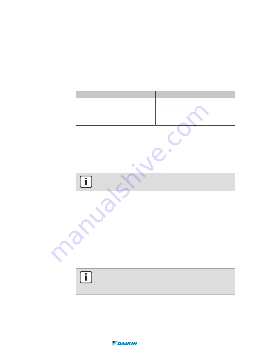
Is the problem solved?
Action
Yes
No further actions required.
No
Return to the troubleshooting of the
specific error and continue with the
next procedure.
3.7 Expansion valve
3.7.1 Outdoor unit expansion valve
Checking procedures
INFORMATION
It is recommended to perform the checks in the listed order.
To perform a mechanical check of the expansion valve
Prerequisite:
Power OFF the unit for 3 minutes. Then turn ON the unit and listen to
the expansion valve assembly. If the expansion valve does NOT make a latching
sound, continue with the electrical check of the expansion valve, see
Prerequisite:
Stop the unit operation via the central controller.
Prerequisite:
Turn OFF the respective circuit breaker.
Prerequisite:
Remove the required plate work, see
315].
1
Remove the expansion valve coil from the expansion valve body, see
INFORMATION
After the check, remove the magnet from the expansion valve body and install the
expansion valve coil on the expansion valve body. Make sure that the expansion
valve coil is firmly slid onto the expansion valve body.
2
Slide the expansion valve magnet over the expansion valve body and gently
rotate the magnet clockwise/counterclockwise to manually close/open the
expansion valve.
Содержание VRV IV+
Страница 473: ......
Страница 474: ......
Страница 475: ......
Страница 476: ...ESIE18 15B 2020 05 Copyright 2020 Daikin Verantwortung für Energie und Umwelt ...


