


Other Control
Si34-601A
124
Function
*
“Master unit”, “slave unit 1” and “slave unit 2” in this section are the names for installation.
They are determined in installation work, and not changed thereafter. (These names are
different from “master unit” and “slave unit” for control.)
The outdoor unit connected the control wires (F1 and F2) for the indoor unit should be
designated as main unit.
Consequently, The LED display on the main PC board for “master unit”, “slave unit 1” and
“slave unit 2” do not change. (Refer to the page 127.)
5.2
Emergency Operation
If the compressor cannot operate, this control inhibits any applicable compressor or outdoor unit
from operating to perform emergency operation only with the operative compressor or outdoor
unit.
5.2.1 Restrictions for Emergency Operation
• In the case of system with 1 outdoor unit installed, only when thermostats of indoor units
having a capacity of 50% or more of the outdoor unit capacity turn ON, the emergency
operation is functional. (If the total capacity of indoor units with thermostat ON is small, the
outdoor unit cannot operate.)
• If the emergency operation is set while the outdoor unit is in operation, the outdoor unit stops
once after pump-down residual operation (a maximum of 5 minutes elapsed).
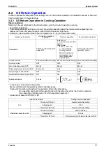
Normal operation
Outdoor unit
rotation
Priority
1
Priority
2
Priority
3
Normal operation
Priority
2
Priority
3
Priority
1
Master Slave 1 Slave 2
Master Slave 1 Slave 2
·
There are outdoor
units that stop
operation.
<In Cooling>
or
·
Low pressure of all
outdoor units in
operation < 0.25 MPa.
Caution
In order to disable the compressor operation due to a failure or else, be sure to do so
in emergency operation mode.
NEVER attempt to disconnect power supply wires from magnetic contactors or else.
(Doing so will operate compressors in combination that disables oil equalization
between the compressors, thus resulting in malfunctions of other normal
compressors.)
Содержание VRV III RXYQ5-54PY1
Страница 1: ...RXYQ5 54PY1 R 410A Heat Pump 50Hz Si34 601A...
Страница 22: ...Si34 601A Specifications 11 Part 2 Specifications 1 Specifications 12 1 1 Outdoor Units 12 1 2 Indoor Units 33...
Страница 72: ...Si34 601A Refrigerant Circuit Refirgerant Circuit 61 RXYQ5P 3D050782 5 6 2 K T E D M N A P O W G J 4 3 1...
Страница 74: ...Si34 601A Refrigerant Circuit Refirgerant Circuit 63 RXYQ8P 3D050783 5 7 6 2 3 1 4 D N A P M O W T E F V G J...
Страница 101: ...Refrigerant Flow for Each Operation Mode Si34 601A 90 Refirgerant Circuit...
Страница 153: ...Outline of Control Indoor Unit Si34 601A 142 Function...
Страница 219: ...Troubleshooting by Remote Controller Si34 601A 208 Troubleshooting...
Страница 226: ...Si34 601A Troubleshooting by Remote Controller Troubleshooting 215...
Страница 325: ...Troubleshooting OP Unified ON OFF Controller Si34 601A 314 Troubleshooting...
Страница 327: ...Piping Diagrams Si34 601A 316 Appendix 1 Piping Diagrams 1 1 Outdoor Unit RXYQ5PY1 3D050782...
Страница 328: ...Si34 601A Piping Diagrams Appendix 317 RXYQ8P 3D050783...
Страница 329: ...Piping Diagrams Si34 601A 318 Appendix RXYQ10P 12PY1 3D050784...
Страница 330: ...Si34 601A Piping Diagrams Appendix 319 RXYQ14P 16P 18PY1 3D050785...
Страница 334: ...Si34 601A Piping Diagrams Appendix 323 FXUQ BEVQ Indoor unit Connection Unit 4D037995F 4D034127B...
Страница 335: ...Wiring Diagrams for Reference Si34 601A 324 Appendix 2 Wiring Diagrams for Reference 2 1 Outdoor Unit RXYQ5PY1 3D050453G...
Страница 336: ...Si34 601A Wiring Diagrams for Reference Appendix 325 RXYQ8PY1 3D050454J...
Страница 337: ...Wiring Diagrams for Reference Si34 601A 326 Appendix RXYQ10PY1 3D050455H...
Страница 338: ...Si34 601A Wiring Diagrams for Reference Appendix 327 RXYQ12PY1 3D051890G...
Страница 339: ...Wiring Diagrams for Reference Si34 601A 328 Appendix RXYQ14P 16P 18PY1 3D050456H...
Страница 340: ...Si34 601A Wiring Diagrams for Reference Appendix 329 2 2 Field Wiring RXYQ5P 8P 10P 12P 14P 16P 18PY1 3D051452D...
Страница 341: ...Wiring Diagrams for Reference Si34 601A 330 Appendix RXYQ20P 22P 24P 26P 28P 30P 32PY1 3D052261B...
Страница 342: ...Si34 601A Wiring Diagrams for Reference Appendix 331 RXYQ34P 36P 38P 40P 42P 44P 46P 48P 50P 52P 54PY1 C 3D052262B...
Страница 343: ...Wiring Diagrams for Reference Si34 601A 332 Appendix 2 3 Indoor Unit FXCQ20M 25M 32M 63MVE 3D039556A...
Страница 344: ...Si34 601A Wiring Diagrams for Reference Appendix 333 FXCQ40M 50M 80M 125MVE 3D039557A...
Страница 345: ...Wiring Diagrams for Reference Si34 601A 334 Appendix FXFQ25M 32M 40M 50M 63M 80M 100M 125MVE 3D039600A...
Страница 346: ...Si34 601A Wiring Diagrams for Reference Appendix 335 FXZQ20M 25M 32M 40M 50M7V1B 3D038359...
Страница 347: ...Wiring Diagrams for Reference Si34 601A 336 Appendix FXKQ25MA 32MA 40MA 63MAVE 3D039564C...
Страница 350: ...Si34 601A Wiring Diagrams for Reference Appendix 339 FXSQ20M 25M 32M 40M 50M 63M 80M 100M 125MVE 3D039561A...
Страница 351: ...Wiring Diagrams for Reference Si34 601A 340 Appendix FXMQ40MA 50MA 63MA 80MA 100MA 125MAVE 3D039620B...
Страница 352: ...Si34 601A Wiring Diagrams for Reference Appendix 341 FXMQ200MA 250MAVE 3D039621B...
Страница 353: ...Wiring Diagrams for Reference Si34 601A 342 Appendix FXHQ32MA 63MA 100MAVE 3D039801D...
Страница 354: ...Si34 601A Wiring Diagrams for Reference Appendix 343 FXAQ20MA 25MA 32MAVE 40MA 50MA 63MAVE 3D034206C...
Страница 356: ...Si34 601A Wiring Diagrams for Reference Appendix 345 FXUQ71MA 100MA 125MAV1 3D044973A...
Страница 357: ...Wiring Diagrams for Reference Si34 601A 346 Appendix FXMQ125MF 200MF 250MFV1 3D044996C...
Страница 358: ...Si34 601A Wiring Diagrams for Reference Appendix 347 BEVQ71MA 100MA 125MAVE 3D044901B...
Страница 381: ...Method of Checking The Inverter s Power Transistors and Diode Modules Si34 601A 370 Appendix...
Страница 395: ...Si34 601A iv Index...