manualshive.com logo in svg
background image

Service manual 

VRV system air conditioner

VAM350J8VEB
VAM500J8VEB
VAM650J8VEB
VAM800J8VEB
VAM1000J8VEB
VAM1500J8VEB
VAM2000J8VEB

EKVDX32A2VEB
EKVDX50A2VEB
EKVDX80A2VEB
EKVDX100A2VEB

draft – 07/02/2022 15:12

Содержание VAM350J8VEB

Страница 1: ...rvice manual VRV system air conditioner VAM350J8VEB VAM500J8VEB VAM650J8VEB VAM800J8VEB VAM1000J8VEB VAM1500J8VEB VAM2000J8VEB EKVDX32A2VEB EKVDX50A2VEB EKVDX80A2VEB EKVDX100A2VEB draft 07 02 2022 15...

Страница 2: ...best of its knowledge No express or implied warranty is given for the completeness accuracy reliability or fitness for particular purpose of its content and the products and services presented therei...

Страница 3: ...log Service manual 3 VAM350 2000J8VEB EKVDX32 100A2VEB VRV system air conditioner ESIE22 07 2022 02 Version log Version code Description Date ESIE22 07 Document release February 2022 draft 07 02 2022...

Страница 4: ...01 11 21 31 Compatibility error between main PCB and fan PCB 37 3 2 23 C6 02 12 22 32 Setting error between main PCB and fan PCB 37 3 2 24 C6 05 15 25 35 Fan PCB EEPROM error 38 3 2 25 C6 06 16 26 36...

Страница 5: ...air outlet 61 4 2 3 Maintenance before a long stop period 61 4 2 4 Maintenance after a long stop period 61 5 Technical data 62 5 1 Detailed information setting mode 62 5 1 1 Detailed information sett...

Страница 6: ...down the system in case of an emergency Name and address of fire department police and hospital Name address and day and night telephone numbers for obtaining service In Europe EN378 provides the nec...

Страница 7: ...inals of main circuit capacitors or electrical components before servicing The voltage MUST be less than 50 V DC before you can touch electrical components For the location of the terminals see the wi...

Страница 8: ...water oil or other substances Protect bystanders from injury and property from possible damage cause by service works WARNING If any work is to be conducted on the refrigerating equipment or any assoc...

Страница 9: ...e sufficient precautions in case of refrigerant leakage If refrigerant gas leaks ventilate the area immediately Possible risks Excessive refrigerant concentrations in a closed room can lead to oxygen...

Страница 10: ...utility pipe surge absorber or telephone earth Incomplete earthing may cause electrical shock WARNING ONLY use copper wires Make sure the field wiring complies with the applicable legislation All fie...

Страница 11: ...nalysis is required prior to re use of recovered refrigerant It is essential that electrical power is available before the task is commenced Become familiar with the equipment and its operation Isolat...

Страница 12: ...and that any associated electrical components are sealed to prevent ignition in the event of a refrigerant release Consult manufacturer if in doubt Do NOT overfill the refrigerant cylinder confirm wi...

Страница 13: ...T place any objects or equipment on top of the unit Do NOT sit climb or stand on the unit 1 5 Notices NOTICE Make sure water quality complies with EU directive 2020 2184 Check the system for leaks aft...

Страница 14: ...of incoming supply air from a VAM heat reclaim ventilation unit For comfort temperature control it is still required to install a normal indoor unit Do not place the EKVDX before the heat reclaim ven...

Страница 15: ...s h Drain pipe i Refrigerant piping transmission cable The EKVDX A DX coil module is a unit based on the FXSA A VRV indoor unit without its fan The new VAM J8 range is mechanically the same as the cur...

Страница 16: ...r to match the diameter of the duct connection of the two units The reducer is placed inside the EKVDX A unit for easier transportation Operation logic a b c d e f VAM EKVDX a Return side b Supply sid...

Страница 17: ...RALIZED SYSTEM VRV F1 F2 F1 F2 P1 P2 P1 P2 VAM J8 VAM J8 EKVDX A VRV DX BRC1H52 82 F1 F2 F1 F2 iTM F1 F2 P1 P2 VAM J8 P1 P2 BRC1H52 82 P1 P2 BRC1H52 82 P1 P2 BRC1H52 82 P1 P2 BRC1H52 82 F1 F2 P1 P2 F1...

Страница 18: ...d EKVDX A unit to indicate system is R410A In this case BRC1H51 81 can be used VAM CAN be installed standalone as well In this case it should have a separate remote controller If centralized control i...

Страница 19: ...vailable on the Daikin Business Portal To retrieve the error code To indicate a system error the controller displays on the messages zone of the home screen b a c a Messages zone b Middle button c Err...

Страница 20: ...re shown on the Notifications screen To check the error history To check the error history with the Madoka Assistant for BRC1H Action Image for reference Result 1 Tap the settings icon The Unit settin...

Страница 21: ...2 of X1M terminal of the indoor unit to check for the correct functioning of the external device Wiring connected to a window or door contact Open circuit unit continues previous operation remote cont...

Страница 22: ...rigerant leak Check saturation pressure of the field piping via the liquid service port and gas stop valve 2 If saturation pressure gas and or liquid outdoor ambient temperature refrigerant leak is pr...

Страница 23: ...rom EEPROM Unit will stop operating Power reset of indoor unit To solve the error code INFORMATION It is recommended to perform the checks in the listed order 1 Perform a power reset If the error disa...

Страница 24: ...heck of the drain pump See Drain pump Possible cause Faulty drain pump 5 Perform a check of the indoor unit main PCB See Indoor unit PCB Possible cause Faulty indoor unit main PCB INFORMATION If all p...

Страница 25: ...solve the error code INFORMATION It is recommended to perform the checks in the listed order 1 Check the power supply to the indoor unit See Power supply Possible cause Faulty or disturbance of the p...

Страница 26: ...solve the error code INFORMATION It is recommended to perform the checks in the listed order 1 Check the power supply to the indoor unit See Power supply Possible cause Faulty or disturbance of the p...

Страница 27: ...M4F A5P 17 VAM1500 2000J8 Exhaust air top M3F A4P To solve the error code INFORMATION It is recommended to perform the checks in the listed order 1 Check the power supply to the indoor unit See Power...

Страница 28: ...t fan PCB 4 Perform a check of the indoor unit main PCB See Indoor unit PCB Possible cause Faulty indoor unit main PCB INFORMATION If all procedures listed above have been performed and the problem is...

Страница 29: ...present contact the helpdesk 3 2 11 A6 29 Airflow rate too low VAM J8 units Trigger Effect Reset The airflow is lower than the threshold level VAM and EKVDX unit will stop operating Power reset To so...

Страница 30: ...alone VAM J8 make sure to perform correct field settings See 5 8 Field settings 483 Possible cause Incorrect field settings 2 Check that the ducting is compliant with the installation limits See insta...

Страница 31: ...se Faulty indoor unit fan PCB 3 Perform a check of the indoor unit fan motors See Indoor unit fan motor Possible cause Faulty indoor unit fan motor 4 Perform a check of the indoor unit main PCB See In...

Страница 32: ...tat OFF The indoor unit with this error will stop refrigerant flow expansion valve OFF and VAM unit will resume fan operation fan ON All other indoor units and outdoor unit will continue operating Pow...

Страница 33: ...d to perform the checks in the listed order 1 Check for excess water level in the drain pan Check drain connector to the common drain pipe and make sure minimum height is respected Empty the drain pan...

Страница 34: ...Short circuit 2 Perform a power reset If the error disappears and is raised again after a while check for the presence of an external source causing electrical noise See External factors Possible cau...

Страница 35: ...See Indoor unit PCB Possible cause Faulty indoor unit main PCB INFORMATION If all procedures listed above have been performed and the problem is still present contact the helpdesk 3 2 19 C1 00 Communi...

Страница 36: ...ulty indoor unit main PCB INFORMATION If all procedures listed above have been performed and the problem is still present contact the helpdesk 3 2 21 C5 00 Gas thermistor abnormality EKVDX A units Tri...

Страница 37: ...the correct spare part is installed for the appropriate indoor unit fan PCB see table above See Indoor unit fan PCB Possible cause Incorrect spare part PCB 2 Check if the correct spare part is install...

Страница 38: ...r the indoor unit main PCB See Indoor unit main PCB Check that the correct capacity setting adapter is connected to X23A of the PCB Possible cause Incorrect spare part PCB or incorrect capacity settin...

Страница 39: ...erformed and the problem is still present contact the helpdesk 3 2 25 C6 06 16 26 36 Fan PCB fin thermistor malfunction VAM J8 units Trigger Effect Reset Fan PCB fin thermistor is open or short circui...

Страница 40: ...on your unit perform a check of the appropriate indoor unit fan PCB see table above See Indoor unit fan PCB Possible cause Faulty indoor unit fan PCB INFORMATION If all procedures listed above have b...

Страница 41: ...the indoor unit main PCB See Indoor unit PCB Possible cause Faulty indoor unit main PCB INFORMATION If all procedures listed above have been performed and the problem is still present contact the help...

Страница 42: ...sensor 2 Check the error history for error code A0 11 see 3 Troubleshooting 419 If A0 11 is found R32 leak detection sensor was replaced after this error and power reconnected Check if field setting 2...

Страница 43: ...t 2 Check the operation time of the R32 leak detection sensor of the faulty indoor unit If operation time is 10 years replace the R32 leak detection sensor See R32 leak detection sensor Possible cause...

Страница 44: ...present contact the helpdesk 3 2 33 CH 10 R32 leak detection sensor replacement to confirm EKVDX A units Trigger Effect Reset The R32 sensor detected disconnection between indoor unit main PCB and R3...

Страница 45: ...ts Trigger Effect Reset Remote controller air thermistor read out is out of range Indoor unit will continue operating using indoor unit air thermistor as input Auto reset To solve the error code INFOR...

Страница 46: ...interface Possible cause Faulty remote controller or faulty transmission wiring between remote controller and indoor unit 3 If possible switch the faulty remote controller with a remote controller fro...

Страница 47: ...t the helpdesk 3 2 37 U8 00 Transmission error between Master and Slave remote controller VAM J8 units Trigger Effect Reset Main PCB detects abnormal missing signal on remote controller transmission l...

Страница 48: ...ration Auto reset At least one other indoor unit on same F1 F2 wiring has an error To solve the error code INFORMATION It is recommended to perform the checks in the listed order 1 Check the indoor un...

Страница 49: ...It is recommended to perform the checks in the listed order 1 Check the databook for compatible remote controllers Connect compatible remote controller Possible cause Incompatible remote controller IN...

Страница 50: ...ssigned to indoor unit 2 Perform a power reset on the central controller and check if error is resolved 3 Using the service monitoring tools check the communication registers INFORMATION If all proced...

Страница 51: ...nsmission error between VAM and EKVDX EKVDX A units Trigger Effect Reset Error detected in transmission between the units Unit will stop operating Power reset To solve the error code INFORMATION It is...

Страница 52: ...ice activated VAM J8 units Trigger Effect Reset Input signal JC J1 on terminal X2M is closed and field setting 28 8 2 or 28 8 3 Unit will continue operating Auto reset To solve the error code INFORMAT...

Страница 53: ...Perform a check of the indoor unit main PCB See Indoor unit PCB Possible cause Faulty indoor unit main PCB INFORMATION If all procedures listed above have been performed and the problem is still prese...

Страница 54: ...aulty indoor unit main PCB INFORMATION If all procedures listed above have been performed and the problem is still present contact the helpdesk 3 2 52 65 02 Outdoor air thermistor out of range VAM J8...

Страница 55: ...door air thermistor See Thermistors Possible cause Faulty outdoor air thermistor 3 Perform a check of the indoor unit main PCB See Indoor unit PCB Possible cause Faulty indoor unit main PCB INFORMATIO...

Страница 56: ...r disappears and is raised again after a while check for the presence of an external source causing electrical noise See External factors Possible cause External source may cause interference 4 Perfor...

Страница 57: ...one by an authorised installer or service agent We recommend performing maintenance at least once a year However applicable legislation might require shorter maintenance intervals NOTICE We recommend...

Страница 58: ...sive pressure and reduced performance See Maintenance of the heat exchange element 460 4 1 3 Maintenance of the air filter NOTICE Do NOT wash the air filter in hot water Do NOT dry the air filter over...

Страница 59: ...pat it with your hand or remove dust with a vacuum cleaner If excessively dirty wash it in water 4 If the air filter is washed remove water completely and allow to dry for 20 to 30 minutes in the shad...

Страница 60: ...in the unit 5 Install the air filters in the unit 6 Install the service cover 4 2 Maintenance for DX units NOTICE Maintenance MUST be done by an authorised installer or service agent We recommend per...

Страница 61: ...and drain pan may occur Pay attention to the cleaning agent that may also corrode other materials of the indoor unit Aluminium copper plastic ABS 4 2 2 Cleaning the air outlet CAUTION Turn off the uni...

Страница 62: ...data 5 1 Detailed information setting mode 5 1 1 Detailed information setting mode Indoor unit See the installer reference guide on business portal for more information 5 1 2 Detailed information set...

Страница 63: ...350 650 F3U Fuse 250 V 6 3 A T VAM800 2000 F4U A2P Fuse 250 V 6 3 A T VAM350 650 HAP Pilot lamp service monitor green K R Magnetic relay L R Reactor M1D Motor damper M2D Motor damper VAM1500 2000 M1F...

Страница 64: ...ptional accessories are being used see wiring diagram of this accessory X35A is connected when optional accessories are being used see wiring diagram of this accessory An EKVDX unit and its correspond...

Страница 65: ...is less than DC50V Measuring points for voltage Measuring points for voltage Printed circuit board Printed circuit board Wiring diagram VAM350 650J8 INFORMATION The diagrams shown in this manual may...

Страница 66: ...echnical data book 2D137285 X70A X3A C7 X1A R3T X4A F2 RED F1U M1D GRN YLW X3A X27A X10A X10A N X2A S1C X29A K2R WHT A2P JC A1P L P1 X1M P2 X5A X6A PS F1 L2R X6A A3P Z1F MSW V1R L1R X1A J3 X2A X22A X3...

Страница 67: ...4A M2D X2A X1A F2 MSW PS SS1 X1A RED A5P X22A K5R P2 M1D J3 P2 JC F1 X4A MSW X6A X27A X2A A4P A2P X4A X2A X28A X2M X6A C7 L1R L2R L4R M2F M4F M3F L3R L N K1R Z1F V1R R3T X5A S1C S2C X6A HAP X10A X10A...

Страница 68: ...in the part code Symbol Meaning Symbol Meaning Circuit breaker Protective earth Connection Protective earth screw Connector A Rectifier Earth Relay connector Field wiring Short circuit connector Fuse...

Страница 69: ...module K R KCR KFR KHuR K M Magnetic relay L Live L Coil L R Reactor M Stepper motor M C Compressor motor M F Fan motor M P Drain pump motor M S Swing motor MR MRCW MRM MRN Magnetic relay N Neutral n...

Страница 70: ...expansion valve coil Y R Y S Reversing solenoid valve coil Z C Ferrite core ZF Z F Noise filter Translation of text on wiring diagram English Translation Notes Notes X35A is connected when optional a...

Страница 71: ...MS M1P X25A P1 P2 F1 F2 T1 T2 P2 P1 t R1T BLK BLK WHT RED GRN BLK BLK BLK BLK X2M X1M N L PE WHT X30A BLK H07RN F A1P RED Q1C Q1R X7A M Y1E CN1 X41A BLK BLK BLK A3P BLK BLK X17A X18A BLK BLK BLK BLK...

Страница 72: ...ect due to changes updates to the unit Correct diagrams are supplied with the unit and can also be found in the technical data book a b c d R1T e c Y1E R3T R2T R5T a Liquid pipe connection port b Gas...

Страница 73: ...k m a b c d e f g h i j k l e n g d i j l o a Supply air i Gas pipe b Discharge air j Liquid pipe c Heat exchanger k Gas thermistor R3T d Electronic expansion valve Y1E l Drain plug e Switch box m Ai...

Страница 74: ...unit VAM350 650J8 a b b d f h h h c e g i i j e g f a c i j i k l m i i j n a Air inlet h Switch box b Exhaust air fan M2F i Air filter c Exhaust air j Crossflow paper heat exchanger d Bypass damper k...

Страница 75: ...h h h c e g i i j e g f a c i j i k l m i i j n a Air inlet h Switch box b Exhaust air fan M1F i Air filter c Exhaust air j Crossflow paper heat exchanger d Bypass damper k Damper motor M1D e Air ret...

Страница 76: ...Exhaust air bottom c Exhaust air top o Damper motor bottom M1D d Bypass damper top p Limit switch bottom S1C e Air return top q Bypass damper bottom f Air return bottom r Damper motor top M2D g Air s...

Страница 77: ...32 100A2VEB VRV system air conditioner ESIE22 07 2022 02 5 5 Switchbox overview EKVDX A a e b c d a Main PCB A1P b R32 leak sensor PCB A3P c Transmission wiring terminal X1M d Power supply wiring term...

Страница 78: ...00J8 C VAM1500 2000J8 a Fan PCB A2P a Main PCB A1P a Main PCB A1P b Reactor L1R b Reactor L2R b Fan PCB A2P c Main PCB A1P c Fan PCB A3P c Fan PCB A4P d Power supply wiring terminal X3M d Fan PCB A2P...

Страница 79: ...5 Technical data Service manual 79 VAM350 2000J8VEB EKVDX32 100A2VEB VRV system air conditioner ESIE22 07 2022 02 5 6 Field information report See next page draft 07 02 2022 15 12...

Страница 80: ...onal information is required Please fill out the following form before contacting your distributor FIELD INFORMATION REPORT Key person information Name Company name Your contact details Phone number E...

Страница 81: ...ct or reimbursement Piping layout Wiring layout simple schematic Unit Installation information Model name Serial number Installation commissioning date Software version user interface Software version...

Страница 82: ...check the Daikin Business Portal authentication required 2 Go to the tab After sales support on the left navigation pane and select Technical support 3 Click the button Service tools An overview of t...

Страница 83: ...ssistant for BRC1H INFORMATION Images are in English and for reference ONLY For more details on the Madoka Assistant please refer to the BRC1H training course material which is available on the Daikin...

Страница 84: ...times Installer mode screen is displayed 4 Select tap the length of time the Madoka Assistant app is set as installer mode Temporary for 30 minutes Indefinite for unlimited time The Madoka Assistant...

Страница 85: ...Tap Field settings The Field settings screen is displayed 3 Tap and select the type for which you want to set the field settings Indoor unit Remote controller Field settings can now be set for the se...

Страница 86: ...g per indoor unit current settings are displayed In the case of group total setting all of Second Code No which may be set are displayed as Second Code No means no function 6 Tap the Second Code No of...

Страница 87: ...system air conditioner ESIE22 07 2022 02 Action Image Result 2 Tap Apply to remote controller Changes are applied to the field settings 3 Tap Apply Changes to the field settings are confirmed 4 Tap R...

Страница 88: ...21 C 22 C 23 C 24 C 25 C 26 C 28 C 30 C 14 24 d 11 Heating blowout temperature setpoint 24 C 26 C 27 C 28 C 29 C 30 C 31 C 32 C 33 C 35 C 37 C 39 C 41 C 43 C 45 C 15 25 00 Drain pump output when cooli...

Страница 89: ...ut Error output and stop operation Forced off Fan forced off Air flow up 10 EKVDX connected h No Yes 13 Cooling set point with EKVDX 13 C 15 C 16 C 17 C 18 C 19 C 20 C 21 C 22 C 23 C 24 C 25 C 26 C 28...

Страница 90: ...No Yes 9 Preheat time extension c 0 minutes 30 minutes 60 minutes 90 minutes 18 28 0 External signal g JC J2 Last command Priority on external input Priority on operation Disable nighttime free cooli...

Страница 91: ...em n OFF ON 1A 0 Fresh up operation k OFF ON a Factory settings are marked with a grey background b In case VAM and EKVDX are combined and the R32 safety system of the VAM is active the nighttime free...

Страница 92: ...order to have a balanced system Models 350 1000 Settings 19 29 2 and 19 29 3 Balance exhaust air and supply air with fan steps 1 15 based on the air flow curves see the databook and the system pressur...

Страница 93: ...heck if the setting was completed successfully by checking if the field setting is changed to 0 02 INFORMATION While activating setting 19 29 0 04 and 19 29 0 05 the unit is set to heat recovery and t...

Страница 94: ...VAM EKVDX P1 P2 F1 F2 P1 P2 F1 F2 P1 P2 F1 F2 P1 P2 F1 F2 b P1 P2 F1 F2 VRV P1 P2 a Outdoor unit b Controller VRV VRV indoor unit EKVDX EKVDX indoor unit VAM VAM heat reclaim ventilation unit NOTICE...

Страница 95: ...emoved because it will keep on searching for the controller signal To resolve the error perform a power reset without the controller connected The optional adapter PCB KRP2A51 must be connected to 1 u...

Страница 96: ...tings Activate below setting for direct duct connection This direct duct configuration ONLY works if P1 P2 is connected Mode number 17 Switch number 5 Position number 07 Other functions Like in a 1 gr...

Страница 97: ...DX indoor unit VAM VAM heat reclaim ventilation unit All control d b e c a X35A P1 P2 P1 P2 P1 P2 a P1 P2 F1 F2 F1 F2 F1 F2 F1 F2 D1 D2 VRV VAM 2 VAM 1 a Controller for air conditioner b Maximum lengt...

Страница 98: ...air conditioner All individual control 2 1 3 4 F1 F2 F1 F2 F1 F2 F1 F2 F1 F2 F1 F2 F1 F2 F1 F2 P1 P2 P1 P2 P1 P2 VAM 1 VAM 2 VRV 1 a P1 P2 a b c d a Controller for air conditioner b Maximum length of...

Страница 99: ...CS302C51 or DCS601C51 or DCM601A51 VAM 1 VAM heat reclaim ventilation unit 1 VAM 2 VAM heat reclaim ventilation unit 2 VAM 3 VAM heat reclaim ventilation unit 3 VRV VRV indoor unit Up to 64 units a co...

Страница 100: ...Single set point shared set point heating and cooling Dual set point set point for heating and cooling 3 Choose guard timer duration using setting 1e 11 4 To switch the temperature with the guard tim...

Страница 101: ...5 Technical data Service manual 101 VAM350 2000J8VEB EKVDX32 100A2VEB VRV system air conditioner ESIE22 07 2022 02 Mode SW SW position Description 17 27 4 1 L H tap 2 UH tap draft 07 02 2022 15 12...

Страница 102: ......

Страница 103: ......

Страница 104: ...draft 07 02 2022 15 12 ESIE22 07 2022 02 Copyright 2022 Daikin Verantwortung f r Energie und Umwelt...
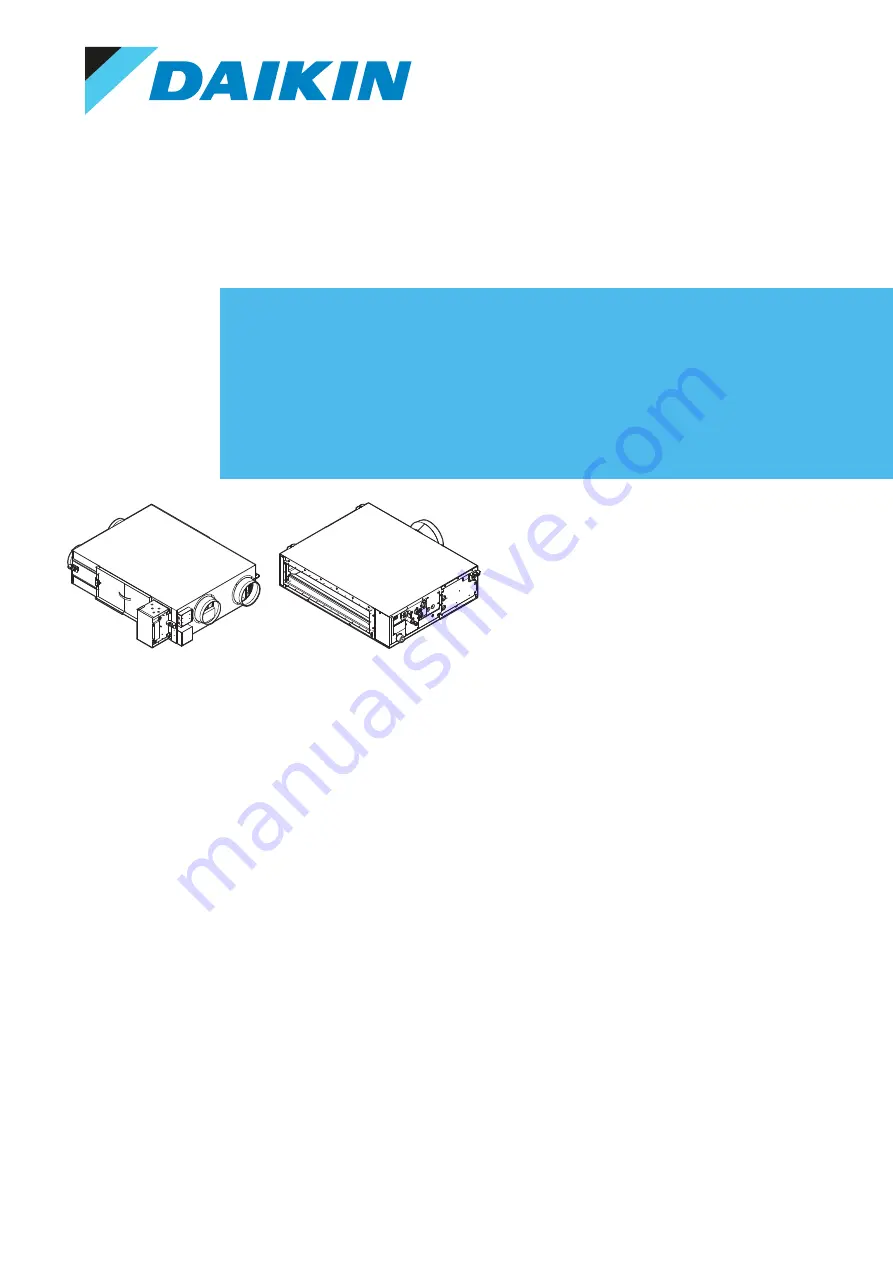
Отзывы: