
IOM 1242-8 • PATHFINDER
®
MODEL AWV CHILLERS
54 www.DaikinApplied.com
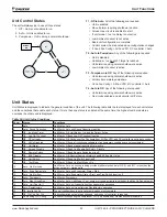
Unit Functions
Unit Functions
Calculations
Evaporator
Error
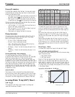
LWT Error = Evaporator LWT - Active LWT Set Point
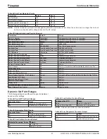
Slope
The slope represents the change or trend in either EWT or
LWT over a time frame of one minute. It is calculated by taking
readings of the temperature every 10 seconds and subtracting
them from the previous value, over a rolling one minute
interval.
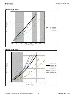
Pulldown Rate
A pulldown rate is calculated by inverting the slope value and
limiting to a minimum value of 0°C/min.
Unit
Capacity
The unit capacity is the total of the circuit target capacities
divided by the number of circuits. This value represents
mechanical cooling capacity of the unit and waterside
economizer capacity is not included.
Total Power
An estimate of the total unit power is calculated by adding the
power estimate for each circuit. All values are in units of kW.
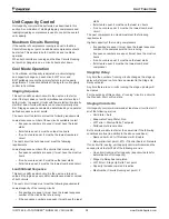
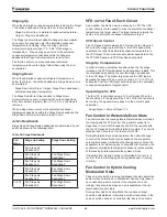
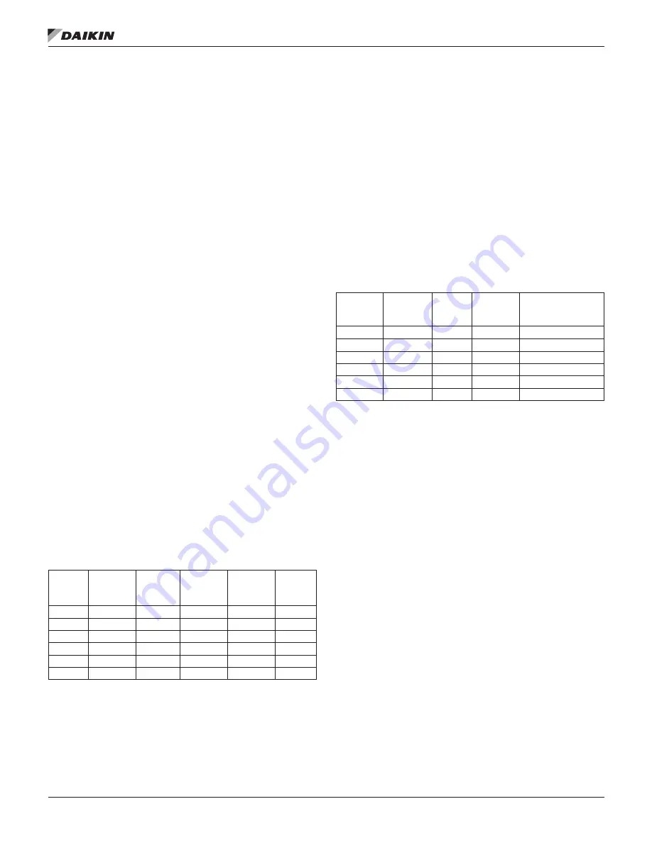
Unit Enable
Enabling and disabling the chiller is accomplished using set
points and inputs to the chiller. The Unit Switch, Remote Switch
Input, and Unit Enable Set Point are all required to be On/
Enable for the unit to be enabled when the control source is
set to Local. The same is true if the control source is set to
Network, with the additional requirement that the BAS Enable
set point be Enable.
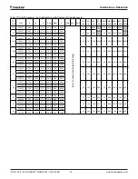
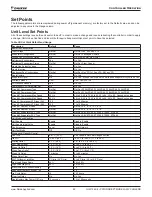
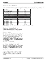
Table 48: Enable Combinations
Unit
Switch
Control
Source
Set Point
Remote
Switch
Input
Unit
Enable
Set Point
BAS
Enable
Set Point
Unit
State
Off
-
-
-
-
Disable
-
-
-
Disable
-
Disable
-
-
Disable
-
-
Disable
On
Local
Enable
Enable
-
Enable
-
Network
-
-
Disable
Disable
On
Network
Enable
Enable
Enable
Enable
NOTE:
A “-” indicates that the value is ignored.
All of the methods for disabling the chiller, discussed in this
section, will cause a normal shutdown of any running circuits.
When the controller is powered up, the Unit Enable Set Point
will be initialized to Disable if the Unit Enable Initial Set Point is
set to Disable. The chiller will remain disabled after powering
up until the Unit Enable Set Point is set to Enable.
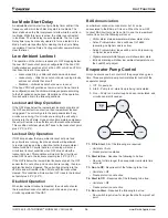
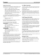
Unit Mode Selection
The operating mode of the unit is determined by set points and
inputs to the chiller. The Available Modes set point determines
what modes of operation can be used. This set point also
determines whether the unit is configured for glycol use. The
Control Source set point determines where a command to
change modes will come from. The Mode Switch digital input
switches between cool mode and ice mode if they are available
and the control source is set to Local. The BAS mode request
switches between cool mode and ice mode if they are both
available and the control source is set to Network.
The Available Modes Set Point should only be changed when
the unit switch is off. This is to avoid changing modes of
operation inadvertently while the chiller is running.
Unit Mode is set according to the following table.
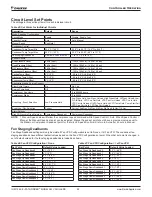
Table 49: Unit Mode Combinations
Available
Modes
Set Point
Control
Source
Set Point
Mode
Switch
BAS
Request
Unit Mode
Cool
-
-
-
Cool
Cool/Ice
Local
Off
-
Cool
Cool/Ice
Local
On
-
Ice
Cool/Ice
Network
-
Cool
Cool
Cool/Ice
Network
-
Ice
Ice
Ice
-
-
Ice
NOTE:
A “-” Indicates that the value is ignored.
Glycol Configuration
If the Available Modes set point is set to an option “w/Glycol,”
then Evaporator Glycol set point must be selected as Yes.
Glycol operation opens up the ranges for several set points to
allow lower values.
Содержание Pathfinder AWV
Страница 4: ...THIS PAGE INTENTIONALLY LEFT BLANK ...


