manualshive.com logo in svg
background image

Installer and user reference guide

Split system air conditioners

English

Installer and user

reference guide

Split system air conditioners

FFA25A2VEB
FFA35A2VEB
FFA50A2VEB
FFA60A2VEB

FFA25A2VEB9
FFA35A2VEB9
FFA50A2VEB9
FFA60A2VEB9

Содержание FFA25A2VEB9

Страница 1: ...ser reference guide Split system air conditioners English Installer and user reference guide Split system air conditioners FFA25A2VEB FFA35A2VEB FFA50A2VEB FFA60A2VEB FFA25A2VEB9 FFA35A2VEB9 FFA50A2VE...

Страница 2: ...electrical wiring 17 6 4 4 Specifications of standard wiring components 17 6 4 5 To connect the electrical wiring on the indoor unit 17 7 Configuration 18 7 1 Field settings 18 8 Commissioning 19 8 1...

Страница 3: ...ildren aged from 8 years and above and persons with reduced physical sensory or mental capabilities or lack of experience and knowledge if they have been given supervision or instruction concerning us...

Страница 4: ...ed Do NOT block any ventilation openings Make sure the unit is level Do NOT install the unit in the following places In potentially explosive atmospheres In places where there is machinery that emits...

Страница 5: ...5 92 6 6 27 6 3 0 76 6 6 6 371 3 2 6 48 6 8 29 3 3 2 87 2 6 8 394 3 4 7 32 7 0 31 0 3 4 98 4 7 0 417 3 6 8 20 7 2 32 8 3 6 110 7 2 441 3 8 9 14 7 4 34 7 3 8 123 7 4 466 4 0 10 1 7 6 36 6 4 0 136 7 6 4...

Страница 6: ...n Open refrigerant cylinders slowly Charge the refrigerant in liquid form Adding it in gas form may prevent normal operation CAUTION When the refrigerant charging procedure is done or when pausing clo...

Страница 7: ...head and make proper tightening impossible Over tightening the terminal screws may break them WARNING After finishing the electrical work confirm that each electrical component and terminal inside th...

Страница 8: ...ter describes what you have to do after the box with the indoor unit is delivered on site Keep the following in mind At delivery the unit MUST be checked for damage Any damage MUST be reported immedia...

Страница 9: ...5 46 C DB 9 21 C DB 10 15 C WB 18 37 C DB 12 28 C WB 10 27 C DB RXS25 60 10 46 C DB 15 24 C DB 16 18 C WB 18 32 C DB 10 30 C DB Outdoor units Cooling Heating 2MXS50 10 46 C DB 15 24 C DB 16 18 C WB 1...

Страница 10: ...ance not accessible to the general public install it in a secured area protected from easy access This unit both indoor and outdoor is suitable for installation in a commercial and light industrial en...

Страница 11: ...ce to the floor see below C 295 mm In case of installation with BYFQ60B 300 mm In case of installation with BYFQ60C a Indoor unit b Lighting the figure shows ceiling mounted lighting but recessed ligh...

Страница 12: ...or installation INFORMATION This chapter only describes installation instructions specific to the indoor unit For the other instructions see The installation manual of the outdoor unit The installatio...

Страница 13: ...5 mm 595 mm 10 mm 12 5 mm A Ceiling opening B Distance between the unit and the ceiling opening C Overlap between the decoration panel and the suspended ceiling Level Make sure the unit is level at a...

Страница 14: ...6 5 2 c e 4 b a d b a d c 3 1 2 6 1 a Drain pipe connection attached to the unit b Drain hose accessory c Metal clamp accessory d Large sealing pad accessory e Insulation piece drain pipe accessory f...

Страница 15: ...refrigerant to be used Only use installation tools e g manifold gauge set that are exclusively used for R32 or R410A installations to withstand the pressure and to prevent foreign materials e g minera...

Страница 16: ...tions Insulation Insulate the refrigerant piping on the indoor unit as follows A B a d c e f b b a d c e f b b 2 4 3 g 1 2 3 4 g A B 1 A Gas piping B Liquid piping a Insulation material field supply b...

Страница 17: ...30 V User interface cable Vinyl cords with 0 75 to 1 25 mm sheath or cables 2 core wires Maximum 500 m 6 4 5 To connect the electrical wiring on the indoor unit NOTICE Follow the wiring diagram delive...

Страница 18: ...t they correspond with the actual installation setup and with the needs of the user Ceiling height Air flow direction Air volume when thermostat control is OFF Time to clean air filter Setting Ceiling...

Страница 19: ...power consumption NOTICE Before starting up the system the unit MUST be energised for at least 6 hours The crankcase heater needs to heat up the compressor oil to avoid oil shortage and compressor bre...

Страница 20: ...it first The backlight is lit for 30 seconds when you press a button 1 Perform introductory steps Action 1 Open the liquid stop valve A and gas stop valve B by removing the stem cap and turning counte...

Страница 21: ...hase power supply units Note Operation will be impossible Turn OFF the power recheck the wiring and switch two of the three electrical wires U4 or UF The inter unit branch wiring is not correct UA The...

Страница 22: ...ESS H P LED V L PILOT LAMP LIGHT EMITTING DIODE HAP LIGHT EMITTING DIODE SERVICE MONITOR GREEN HIGH VOLTAGE HIGH VOLTAGE IES INTELLIGENT EYE SENSOR IPM INTELLIGENT POWER MODULE K R KCR KFR KHuR K M MA...

Страница 23: ...ce see the operation manual of the installed user interface 13 Before operation WARNING This unit contains electrical and hot parts WARNING Before operating the unit be sure the installation has been...

Страница 24: ...n It may take longer to reach the set temperature for general heating operation than for cooling operation The following operation is performed in order to prevent the heating capacity from dropping o...

Страница 25: ...lades while the swing flap is in operation Fingers may become caught or the unit may break down NOTICE The movable limit of the flap is changeable Contact your dealer for details only for double flow...

Страница 26: ...result in burnout of these components 16 1 Cleaning the air filter suction grille air outlet and outside panels 16 1 1 To clean the air filter When to clean the air filter Rule of thumb Clean every 6...

Страница 27: ...in order to dry the interior of the units Refer to 14 2 2 About cooling heating fan only and automatic operation on page 24 for details on fan only operation Turn off the power The user interface dis...

Страница 28: ...face and switches 25 000 hours Drain pan 8 years Expansion valve 20 000 hours Solenoid valve 20 000 hours The table assumes the following conditions of use Normal use without frequent starting and sto...

Страница 29: ...N OFF button on the user interface is pressed If the operation lamp lights the system is in normal condition To prevent overloading of the compressor motor the air conditioner starts 5 minutes after i...

Страница 30: ...s is to prevent refrigerant from remaining in the compressor The unit will stop after 5 to 10 minutes 18 Relocation Contact your dealer for removing and reinstalling the total unit Moving units requir...

Страница 31: ......

Страница 32: ...4P550955 4 2018 08 Copyright 2017 Daikin...
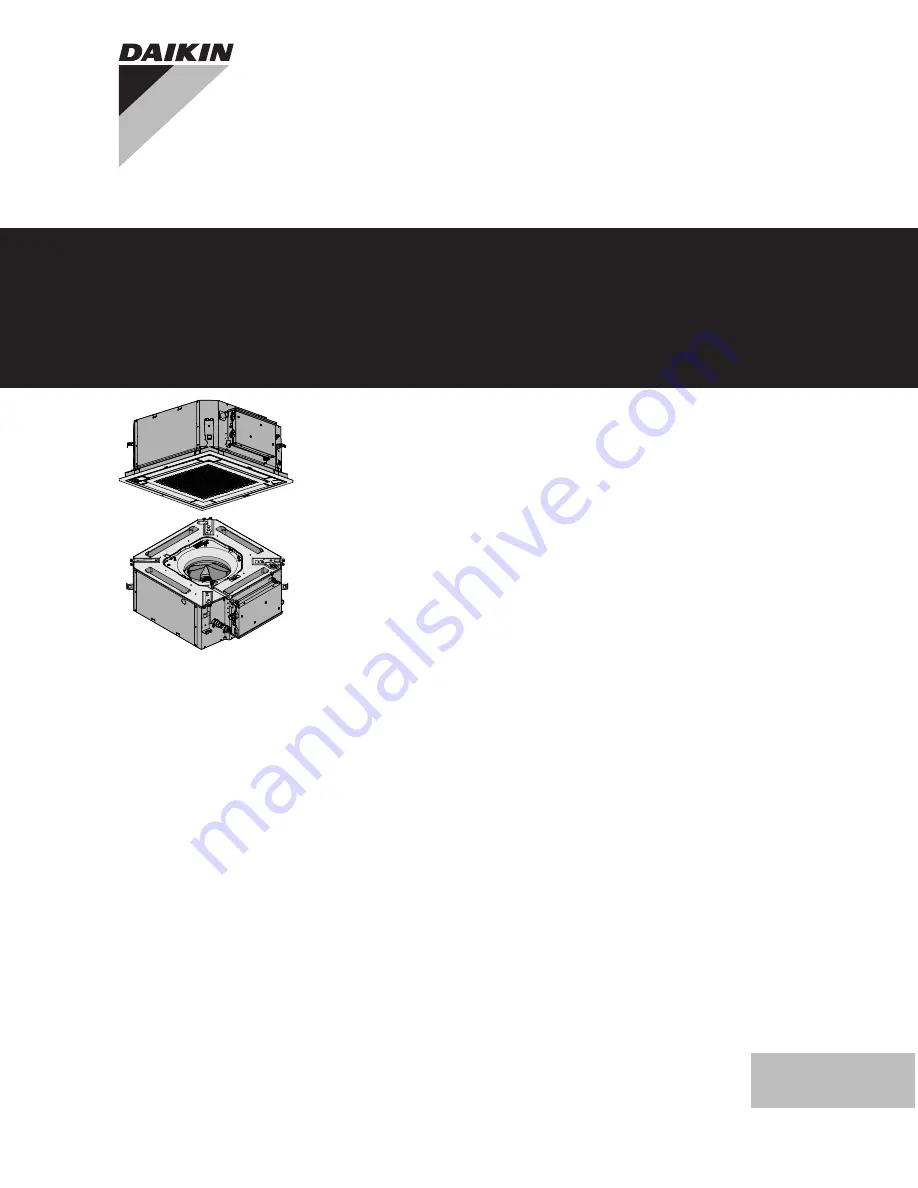
Отзывы: