


D
–EIMHP01201-18_04EN - 16/24
NOTE: Daikin cannot be considered responsible in case of malfunctions generated by hot air recirculation or insufficient
airflow as result of improper installation if the above recommendations are ignored.
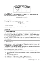
3.5
Noise and sound protection
The unit is a source of noise mainly due to rotation of compressors and fans.
The noise level for each model size is listed in sales documentation.
If the unit is correctly installed, operated and maintained the noise emission level do not require any special protection
device to operate continuously close to the unit without any risk.
In cases where the installation is subject to compliance with special sound requirements, it may be necessary to use
additional noise attenuation devices, it is necessary to isolate the unit from its base with extreme care, correctly applying
the anti-vibration elements (supplied as optional). Flexible joints must be installed on the water connections, as well.
3.6
Water piping
Piping must be designed with the lowest number of elbows and the lowest number of vertical changes of direction. In this
way, installation costs are reduced considerably and system performance is improved.
The water system must have:
1. Anti-vibration mountings in order to reduce transmission of vibrations to the structures.
2. Isolating valves to isolate the unit from the water system during maintenance.
3. Flow switch, in order to protect the unit must be protected against freezing by continuous monitoring of the water flow
in the evaporator. In most cases, on-site the flow switch is set to produce an alarm only when the water pump switches
OFF and the water flow fall to zero. it is recommended to adjust the flow switch in order to produce a “Water Loss
Alarm” when the water flow reaches 50% of the nominal value, in this case the evaporator is protected against the
freezing and the flow switch can detect the water filter clogging.
4. Manual or automatic air venting devic
e at the system’s highest point; drain device at the system’s lowest point.
5.
Neither the evaporator nor the heat recovery device must be positioned at the system’s highest point.
6. A suitable device that can maintain the water system under pressure (expansion tank, etc.).
7. Water temperature and pressure indicators to assist the operator during service and maintenance.
8. A filter or device that can remove particles from the fluid. The use of a filter extends the life of the evaporator and pump
and helps to keep the water system in a better condition.
The water filter must be installed as close as possible to
the unit
, as in Fig. 7. If the water filter is installed in another part of the water system, the Installer has to guarantee the
cleaning of the water pipes between the water filter and the evaporator.
9. Recommended maximum opening for strainer mesh is:
•
0,87 mm (DX S&T)
•
1,0 mm (BPHE)
•
1,2 mm (Flooded)
10. Evaporator and condenser have an electrical resistance with a thermostat that ensures protection against water
freezing at ambient temperatures as low as
–16°C.
11. All the other water piping/devices outside the unit must therefore be protected against freezing.
12. The heat recovery device must be emptied of water during the winter season, unless an ethylene glycol mixture in
appropriate percentage is added to the water circuit.
13. If case of unit substitution, the entire water system must be emptied and cleaned before the new unit is installed.
Regular tests and proper chemical treatment of water are recommended before starting up the new unit.
14. In the event that glycol is added to the water system as anti-freeze protection, pay attention to the fact that suction
pressure will be lower, the unit
’s performance will be lower and water pressure drops will be greater. All unit-protection
systems, such as anti-freeze, and low-pressure protection will need to be readjusted.
15. Before insulating water piping, check that there are no leaks.
3.7
Water treatment
Before putting the unit into operation, clean the water circuit.
The evaporator and the condenser must not be exposed to flushing velocities or debris released during flushing. It is
recommended that a suitably sized bypass and valve arrangement is installed to allow flushing of the piping system. The
bypass can be used during maintenance to isolate the heat exchanger without disrupting flow to other units.
Any damage due to the presence of foreign bodies or debris in the shell&tube heat exchangers will not be covered
by warranty
. Dirt, scales, corrosion debrits and other material can accumulate inside the heat exchanger and reduce its
heat exchanging capacity. Pressure drop can increase as well, thus reducing water flow. Proper water treatment therefore
reduces the risk of corrosion, erosion, scaling, etc.. The most appropriate water treatment must be determined locally,
according to the type of system and water characteristics.
The manufacturer is not responsible for damage to or malfunctioning of equipment caused by failure to treat water or by
improperly treated water.
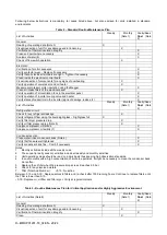
Table 1 - Acceptable water quality limits
pH (25°C)
6,8
8,0
Total Hardness (mg CaCO
3
/ l)
200
Electrical conductivity
S/cm (25°C)
800
Iron (mg Fe / l)
1.0
Chloride ion (mg Cl
-
/ l)
200
Sulphide ion (mg S
2 -
/ l)
None
Sulphate ion (mg SO
2
4
-
/ l)
200
Ammonium ion (mg NH
4
+
/ l)
1.0
Alkalinity (mg CaCO
3
/ l)
100
Silica (mg SiO
2
/ l)
50


