D
–EIMHP01201-18_04EN - 13/24
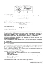
Fig. 4 - Unit Levelling
For installation on the ground, a strong concrete base, at least 250 mm thickness and wider than the unit must be provided.
This base must be able to support the weight of the unit.
The unit must be installed above antivibrating mounts (AVM), rubber or spring types. The unit frame must be perfectly
levelled above the AVM.
Installation such as in the figure above must always be avoided. In case the AV
M’s are not adjustable the flatness of the
unit frame must be guaranteed by using metal plate spacers.
Before unit commissioning, the flatness must be verified by using a laser levelling device or other similar devices. The
flatness shall not be over 5 mm for units within 7 m length and 10 mm for units over 7 m.
If the unit is installed in places that are easily accessible to people and animals, it is advisable to install protection grids for
the condenser and compressor sections.
To ensure best performance on the installation site, the following precautions and instructions must be followed:
−
Avoid air flow recirculation.
−
Make sure that there are no obstacles to hamper air flow.
−
Make sure to provide a strong and solid foundation to reduce noise and vibrations.
−
Avoid installation in particularly dusty environments, in order to reduce soiling of condensers coils.
−
The water in the system must be particularly clean and all traces of oil and rust must be removed. A mechanical water
filter must be installed on the unit
’s inlet piping.
3.4
Minimum space requirements
It is fundamental to respect minimum distances on all units in order to ensure optimum ventilation to the condenser. Limited
installation space could reduce the normal air flow, thus significantly reducing the machine’s performance and considerably
increasing consumption of electrical energy.
When deciding where to position the machine and to ensure a proper air flow, the following factors must be taken into
consideration: avoid any warm air recirculation and insufficient air supply to the air-cooled condenser.
Both these conditions can cause an increase of condensing pressure, which leads to a reduction in energy efficiency and
refrigerating capacity. Thanks to the geometry of their air-cooled condensers, the units are less affected by poor air
circulation conditions.
Also, the
software has particularly the ability to compute the machine’s operating conditions to optimise the load under
abnormal operating circumstances.
Every side of the machine must be accessible for post-installation maintenance operations. Figure 4 shows the minimum
space required.
Vertical air discharge must not be obstructed as this would significantly reduce capacity and efficiency.
If the machine is surrounded by walls or obstacles of the same height as the machine, it must be installed at a distance of
at least 2500 mm. If these obstacles are higher, the machine must be installed at a distance of at least 3000 mm.
Should the machine be installed without observing the recommended minimum distances from walls and/or vertical
obstacles, there could be a combination of warm air recirculation and/or insufficient supply to the air-cooled condenser
which could cause a reduction of capacity and efficiency.
In any case, the microprocessor will allow the machine to adapt itself to new operating conditions and deliver the maximum
capacity available under any given circumstances, even if the lateral distance is lower than recommended.


