


General Outline
ESIE10-01
1–92
3
11
4
5
1.34
Electrical Installation
General
specifications
Caution:
Q
All electrical connections to the machine must be carried out in compliance with laws and
regulations in force. All installation, operating and maintenance activities must be carried out by
qualified personnel. Please refer to the specific wiring diagram for the machine that you have
purchased and which was sent with the unit. Should the wiring diagram not appear on the machine
or should it have been lost, please contact your dealer who will provide for a copy to be forwarded.
Q
Use copper conductors only. Failure to use copper conductors could cause overheating or
corrosion at the connection points and damage the unit. To avoid interference, all control wires
must be installed separately from the power wires. Use separate electrical conduits for this
purpose.
Q
Before servicing the machine in any way, open the general disconnecting switch on the machine's
main power supply. When the machine is off but the disconnector switch is in the closed position,
unused circuits are live as well. Never open the terminal board box of the compressors before
having opened the unit's general disconnecting switch.
Q
Series units are fitted with high power non-linear electrical components (VPD compressor supply).
These cause superior harmonics and can cause significant leakage towards ground (about 2 A).
The protection for the power supply system must be designed in accordance with the
above-mentioned values.
Q
The short circuit current that can be withstood by the electrical board in accordance with
EN 60439-1, is 25 kA. Please therefore check the short-circuit current at the machine power supply
line connection terminals to ensure that it is less than or equal to the machine panel hold current.
Q
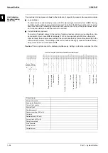
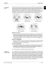
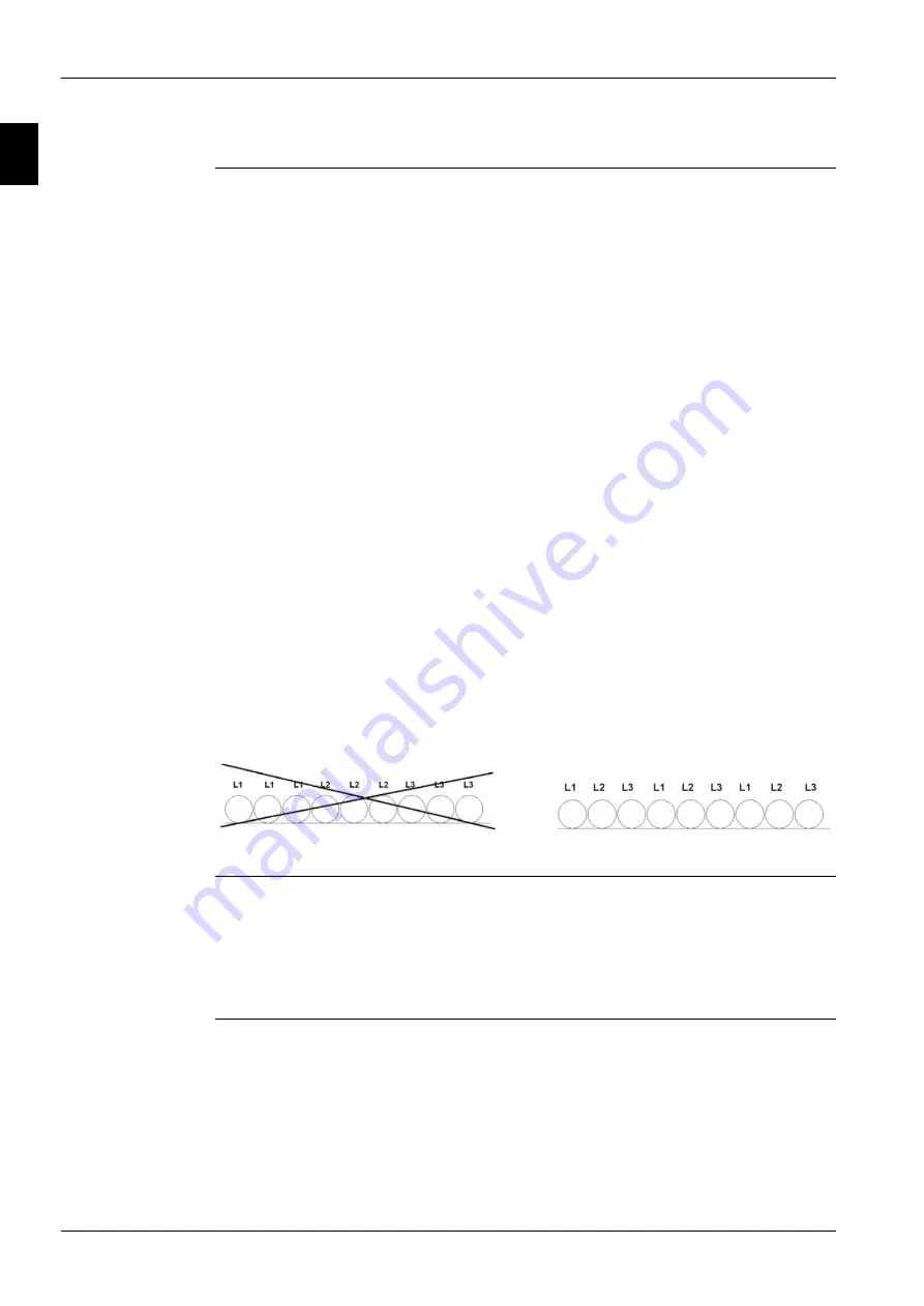
In installations with power supply lines longer than 50 metres, inductive coupling between phases
and between phase and earth generates significant phenomena, namely:
•
Unbalancing of phase currents
•
Excessive voltage drop
In order to limit these phenomena, it is good practise to lay out the phase wires symmetrically, as
described in the figure.
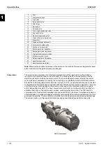
Electrical
components
All power and interface electrical connections are specified in the wiring diagram that is shipped with
the machine. The installer must supply the following components:
Q
Power supply wires (dedicated conduit).
Q
Interconnection and interface wires (dedicated conduit).
Q
Thermal-magnetic circuit breaker of suitable size (please see electrical data).
Electrical wiring
Power circuit:
Connect the electrical power supply cables to the terminals of the general circuit breaker on the
machine's terminal board. The access panel must have a hole of appropriate diameter for the cable
used and its cable gland. A flexible conduit can also be used, containing the three power phases plus
earth. In any case, absolute protection against water penetrating through the connection point must
be ensured.
NO
OK
Installation of long power supply wires
Содержание EWAD620-C17C-SS
Страница 2: ......
Страница 8: ...ESIE10 01 1 2 Part 1 System Outline 3 1 1 5...
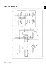
Страница 111: ...ESIE10 01 General Outline Part 1 System Outline 1 105 3 1 4 5 1 36 1 Power Compressor 1 2...
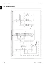
Страница 112: ...General Outline ESIE10 01 1 106 Part 1 System Outline 3 1 1 4 5 1 36 2 Power Compressor 3...
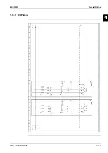
Страница 113: ...ESIE10 01 General Outline Part 1 System Outline 1 107 3 1 4 5 1 36 3 Kit Pumps...
Страница 114: ...General Outline ESIE10 01 1 108 Part 1 System Outline 3 1 1 4 5 1 36 4 Circuit Fan Power Supply 1...
Страница 115: ...ESIE10 01 General Outline Part 1 System Outline 1 109 3 1 4 5 1 36 5 Circuit Fan Power Supply 1...
Страница 116: ...General Outline ESIE10 01 1 110 Part 1 System Outline 3 1 1 4 5 1 36 6 Circuit Fan Power Supply 2...
Страница 117: ...ESIE10 01 General Outline Part 1 System Outline 1 111 3 1 4 5 1 36 7 Circuit Fan Power Supply 2...
Страница 118: ...General Outline ESIE10 01 1 112 Part 1 System Outline 3 1 1 4 5 1 36 8 Circuit Fan Power Supply 3...
Страница 119: ...ESIE10 01 General Outline Part 1 System Outline 1 113 3 1 4 5 1 36 9 Circuit Fan Power Supply 3...
Страница 120: ...General Outline ESIE10 01 1 114 Part 1 System Outline 3 1 1 4 5 1 36 10 Unit Control Circuit Power Supply...
Страница 121: ...ESIE10 01 General Outline Part 1 System Outline 1 115 3 1 4 5 1 36 11 Analog Inputs Output Board...
Страница 122: ...General Outline ESIE10 01 1 116 Part 1 System Outline 3 1 1 4 5 1 36 12 Digital Inputs Board...
Страница 123: ...ESIE10 01 General Outline Part 1 System Outline 1 117 3 1 4 5 1 36 13 Digital Outputs Board...
Страница 124: ...General Outline ESIE10 01 1 118 Part 1 System Outline 3 1 1 4 5 1 36 14 Digital Outputs Board...
Страница 125: ...ESIE10 01 General Outline Part 1 System Outline 1 119 3 1 4 5 1 36 15 Extension Control Fans 1 2...
Страница 126: ...General Outline ESIE10 01 1 120 Part 1 System Outline 3 1 1 4 5 1 36 16 Extension Control Fans 3...
Страница 127: ...ESIE10 01 General Outline Part 1 System Outline 1 121 3 1 4 5 1 36 17 Extension Control Fans 4...
Страница 128: ...General Outline ESIE10 01 1 122 Part 1 System Outline 3 1 1 4 5 1 36 18 Expansion Input Output Unit Alarm Limiting...
Страница 129: ...ESIE10 01 General Outline Part 1 System Outline 1 123 3 1 4 5 1 36 19 Expansion Control Compressor 1...
Страница 130: ...General Outline ESIE10 01 1 124 Part 1 System Outline 3 1 1 4 5 1 36 20 Expansion Control Compressor 1...
Страница 131: ...ESIE10 01 General Outline Part 1 System Outline 1 125 3 1 4 5 1 36 21 EEXV Compressor 1...
Страница 132: ...General Outline ESIE10 01 1 126 Part 1 System Outline 3 1 1 4 5 1 36 22 Expansion Control Compressor 2...
Страница 133: ...ESIE10 01 General Outline Part 1 System Outline 1 127 3 1 4 5 1 36 23 Expansion Control Compressor 2...
Страница 134: ...General Outline ESIE10 01 1 128 Part 1 System Outline 3 1 1 4 5 1 36 24 EEXV Compressor 2...
Страница 135: ...ESIE10 01 General Outline Part 1 System Outline 1 129 3 1 4 5 1 36 25 Expansion Control Compressor 3...
Страница 136: ...General Outline ESIE10 01 1 130 Part 1 System Outline 3 1 1 4 5 1 36 26 Expansion Control Compressor 3...
Страница 137: ...ESIE10 01 General Outline Part 1 System Outline 1 131 3 1 4 5 1 36 27 EEXV Compressor 3...
Страница 138: ...General Outline ESIE10 01 1 132 Part 1 System Outline 3 1 1 4 5 1 36 28 Pumps Control...
Страница 139: ...ESIE10 01 General Outline Part 1 System Outline 1 133 3 1 4 5 1 36 29 Terminals M1 M2...
Страница 140: ...General Outline ESIE10 01 1 134 Part 1 System Outline 3 1 1 4 5 1 36 30 Terminals M3...
Страница 141: ...ESIE10 01 General Outline Part 1 System Outline 1 135 3 1 4 5 1 36 31 Terminals M5 MQ...
Страница 148: ...General Outline ESIE10 01 1 142 Part 1 System Outline 3 1 1 4 5...
Страница 150: ...ESIE10 01 2 2 Part 2 Functional Description 3 1 2 5...
Страница 170: ...The Digital Controller ESIE10 01 2 22 Part 2 Functional Description 3 1 2 4 5...
Страница 200: ...Functional Control ESIE10 01 2 52 Part 2 Functional Description 3 1 2 4 5...
Страница 202: ...ESIE10 01 3 2 Part 3 Troubleshooting 3 1 3 5...
Страница 254: ...Alarms and Events ESIE10 01 3 54 Part 3 Troubleshooting 3 1 3 4 5...
Страница 266: ...Controller Inputs and Outputs ESIE10 01 3 66 Part 3 Troubleshooting 3 1 3 4 5...
Страница 280: ...ESIE10 01 4 2 Part 4 Commissioning and Test Run 3 1 4 5...
Страница 286: ...Pre Test Run Checks ESIE10 01 4 8 Part 4 Commissioning and Test Run 3 1 4 5...
Страница 289: ...ESIE10 01 Running Data Part 4 Commissioning and Test Run 4 11 3 4 5 1...
Страница 290: ...Running Data ESIE10 01 4 12 Part 4 Commissioning and Test Run 3 1 4 5...
Страница 292: ...ESIE10 01 5 2 Part 5 Maintenance 3 1 5...


